A gateway on a test bench
Our primary car steers significantly stiffer than the e-Golf. This is something I could change using VCDS by adjusting it to a different value. However, on the e-Golf, this is managed using driving profiles. The e-Golf only has three profiles that cannot be changed:
- Normal: normal steering
- Eco: normal steering
- Eco+: very stiff steering
These profiles are managed by the gateway, and it turns out there is a
project that can adapt these so-called FPAs, which is a German acronym
for ‘fahrprofilauswahl’. The requirements? A gateway with software
3Q0 907 530 Q or higher.
Unfortunately, my car was equipped with 3Q0 907 530 H based on hardware
3Q0 907 530 D. I could find a flash file with index AA, BB, or BF, but
I did not want to potentially damage the original part. I searched for
second-hand parts and found one with index AD from an e-Golf as well. This
saved me the trouble of finding the correct dataset.
Test bench
Having an additional gateway also provides the option to start building a test bench. That way, I can test and configure replacement parts before installing them in the car. Building a test bench is not straightforward, but it is achievable.
Every test bench requires a gateway. It is the module that interconnects all
the different CAN bus networks together, including the diagnostics port. Next
to the gateway, you need a method to wake up additional devices. This is
normally the responsibility of the steering column switch, which I do not have.
Luckily, someone built a DIY solution that emulates this component by
sending the so-called Klemmen_Status_01 message. This message wakes up other
devices, based on the ignition status in an actual setup.
I obtained the necessary parts to start building the test setup. I acquired a 20-pin gateway connector from an older PQ35 vehicle, which still fits with the MQB vehicles. Using an Arduino, two relays, and a CAN bus adapter, I was able to wake up other devices. The relays are not necessary, but I used that to switch terminal 30 and terminal 15. First, both terminals get switched off, then terminal 30 is switched, and after a few seconds terminal 15. This way, I can cycle the power in a correct order.
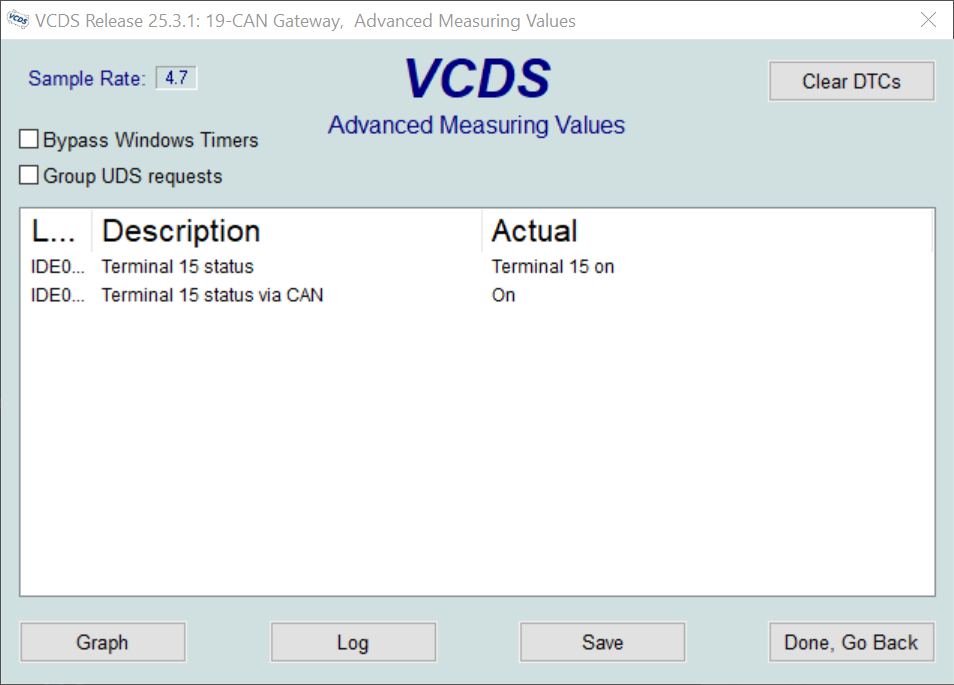
Using VCDS, you can verify this by going to ‘Measure values’ and looking for ‘Terminal 15 status via CAN’. Several modules have this option. I did this for the gateway module (J533, or block 19).
This setup allowed me to provision the gateway in advance. I compared both adaption maps and found only minor differences, most of which were related to installed equipment.
Strictly speaking, I probably did not need the emulation part to interact with the gateway, since this component is ‘always on’. However, I have other plans that will require this solution.
Pinout
For anyone who wants to build a similar setup, this is how I connected this:
16-pin ODB-2 connector (T16 for U31):
- T16/1 -> Terminal 15 (Relay 2/NO)
- T16/4 -> Terminal 31 (ground)
- T16/5 -> Terminal 31 (ground)
- T16/6 -> T20/19 (Diagnostic CAN bus high)
- T16/14 -> T20/9 (Diagnostic CAN bus low)
- T16/16 -> Terminal 30 (Relay 1/NO)
20-pin gateway connector (T20 for J533):
- T20/1 -> Terminal 30 (Relay 1/NO)
- T20/5 -> MCP2515/low (Comfort CAN bus low)
- T20/9 -> T16/14 (Diagnostic CAN bus low)
- T20/11 -> Terminal 31 (ground)
- T20/12 -> Terminal 31 (ground)
- T20/15 -> MCP2515/high (Comfort CAN bus high)
- T20/19 -> T16/6 (Diagnostic CAN bus high)
Relay board:
- Relay 1/Commmon -> 12 V
- Relay 1/NO -> Terminal 30
- Relay 2/Common -> 12 V
- Relay 2/NO -> Terminal 15
MCP2515 board:
- MCP2515/low -> T20/5 (Comfort CAN bus low)
- MCP2515/high -> T20/15 (Comfort CAN bus high)