High-line camera upgrade (part 5)
Although I have been using the high-line rear view camera for a while now, I still had to finalize the wiring. The eight-pin connector (T8aj) needed power, which I took from the four-pin connector (T4bt) from the low-line camera, but I planned to use the T4d connector from the servo motor to power the camera. This way, I had a one-cable solution. I have the details for the wiring and the connectors in part 3, so I will not repeat them here.
I took some time to see how I would route the wires. I decided to route them as shown in the picture below. Given that there is sound-damping material in the trim pieces that go over this, I think it will be fine.
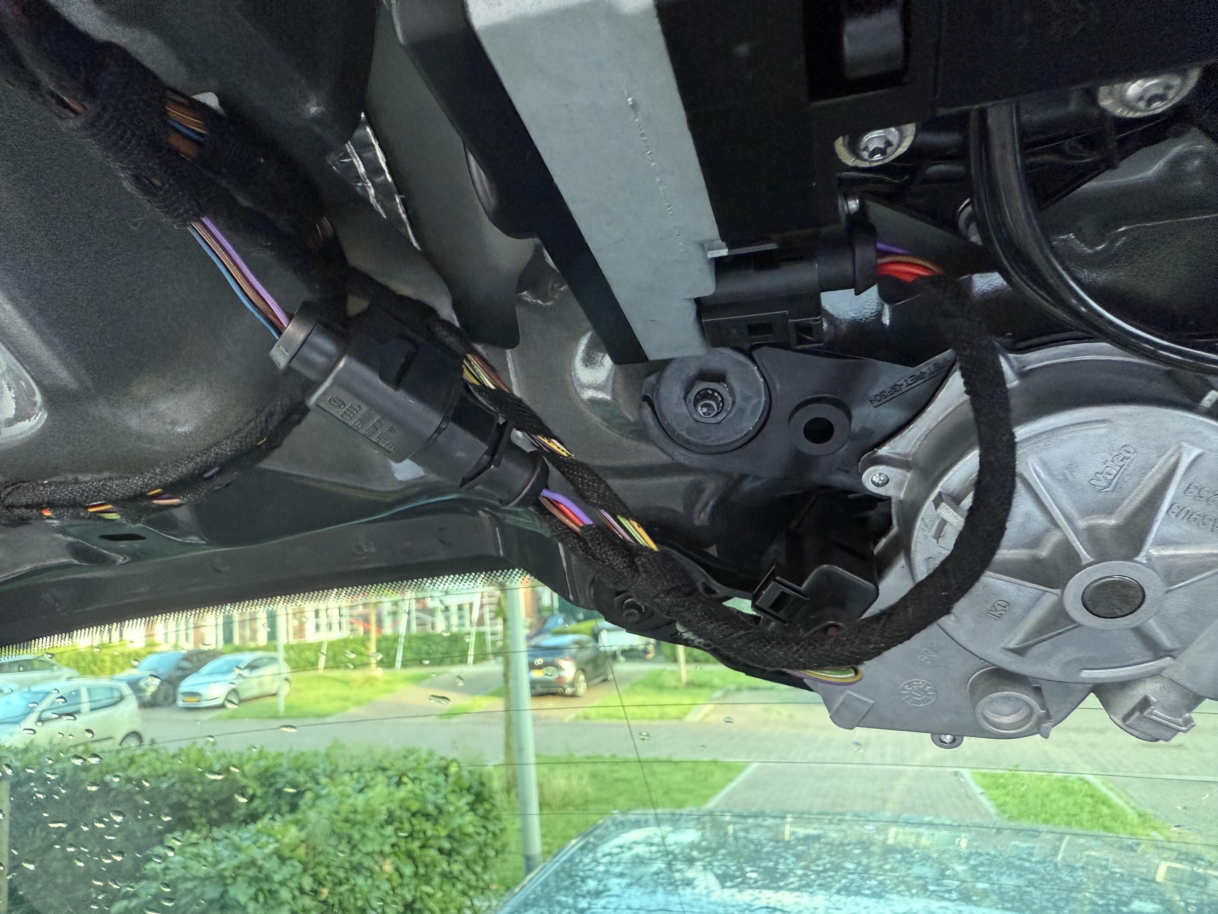
I decided to splice the power wires directly at the connector pins, which is not recommended when using rubber seals. But given that there are other connectors in the same area without rubber seals, I think it will be fine.
Improved bracket
When I replaced the low-line camera with the high-line camera, I used a 3D-printed bracket to hold the camera in place, given that the positions of the screws are different. When I installed the camera and calibrated it, I noticed that the image was a bit tilted, as can be seen in part 4. Back than I did not think much of it, because calibration solved this. But over the course of time, I also noticed that there was much play when the camera was engaged.
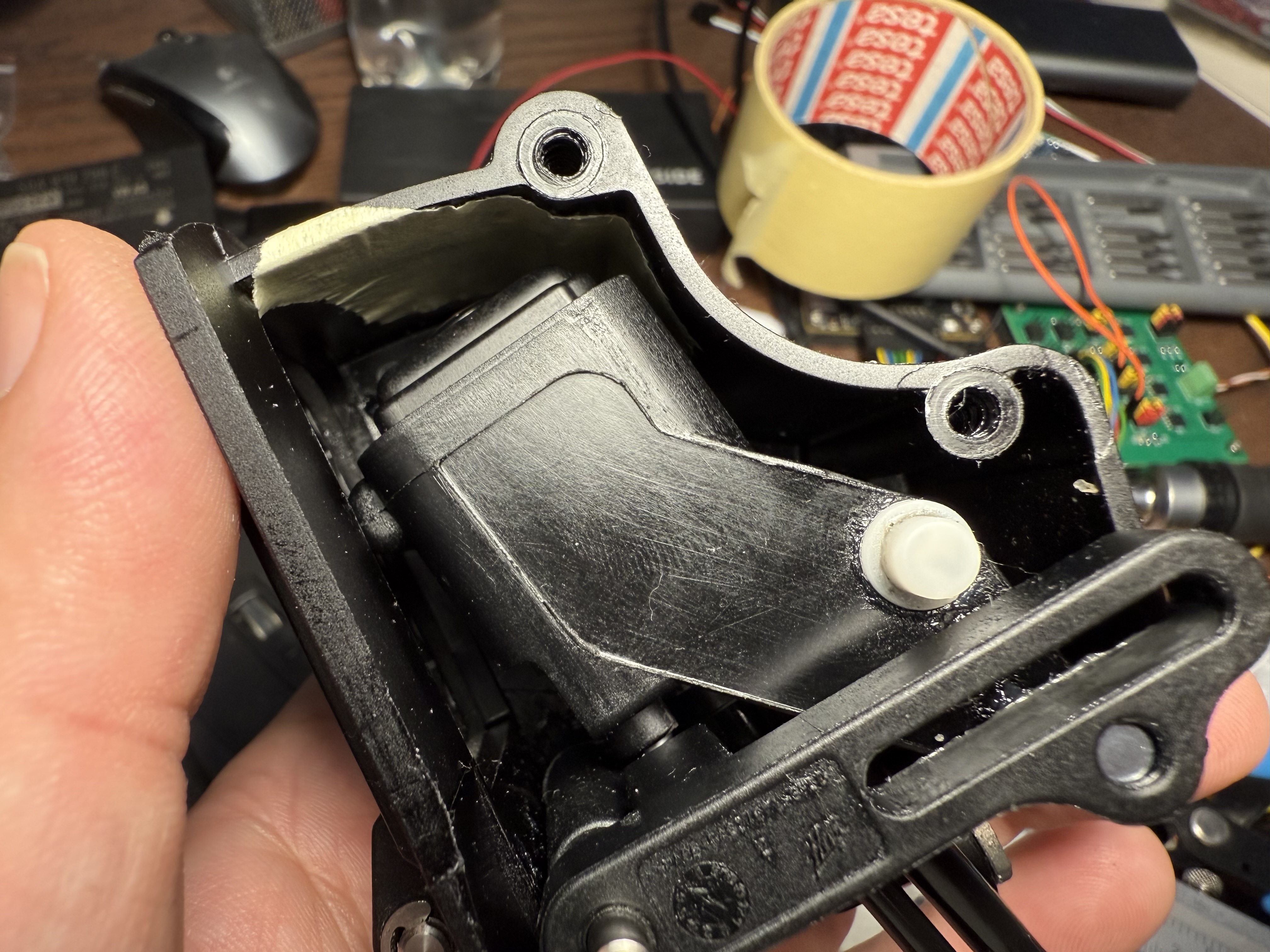
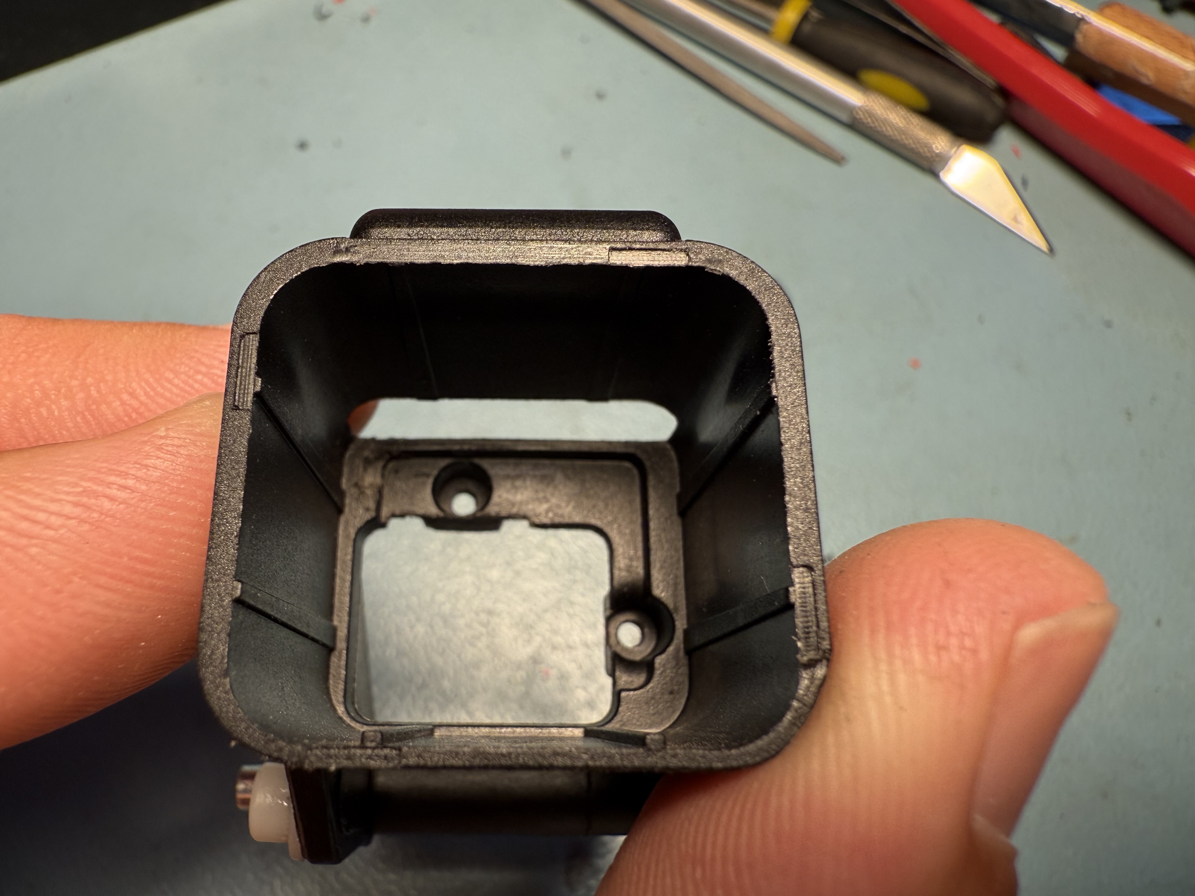
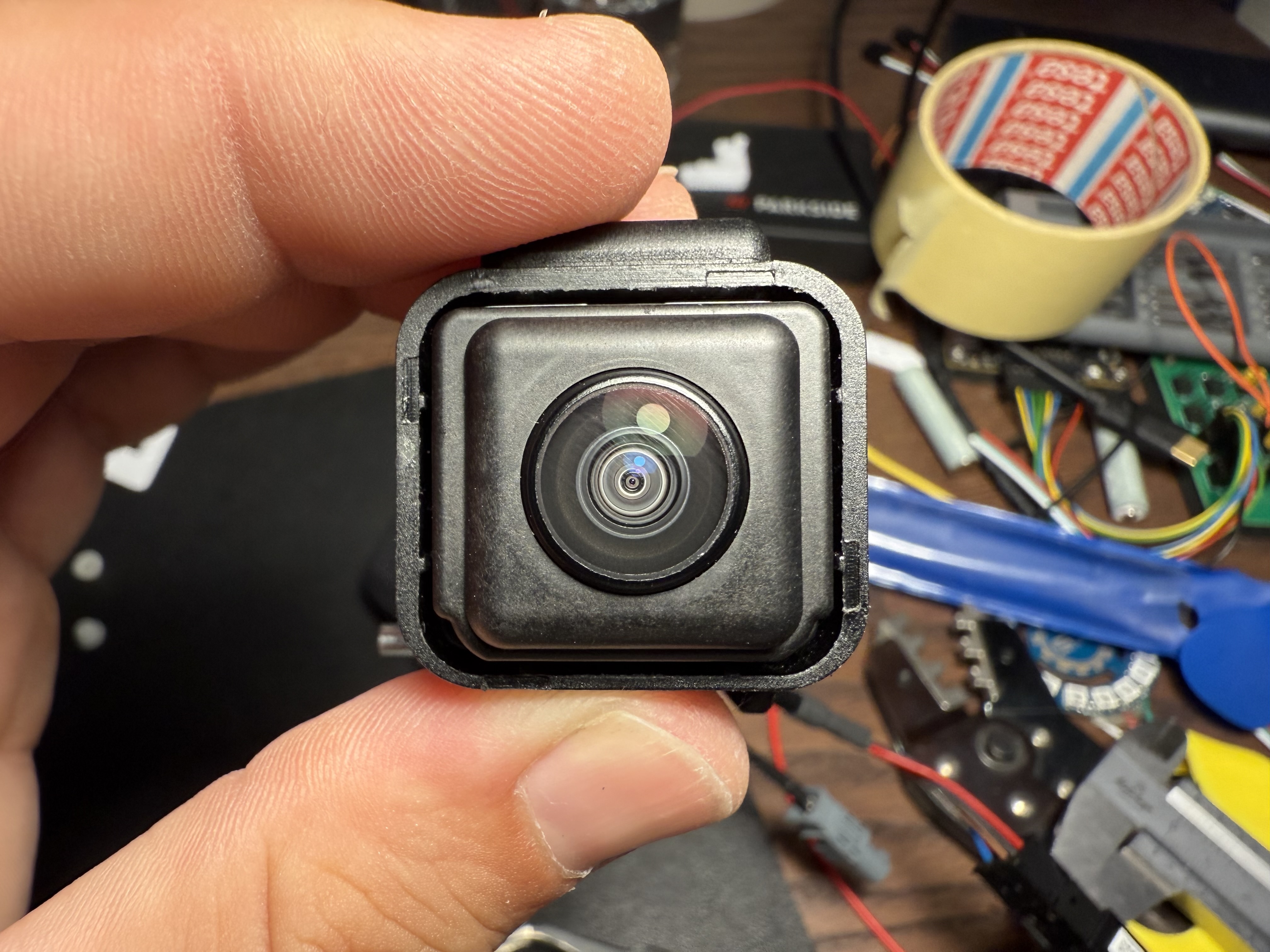
I decided to see if I could make it more sturdy, but I quickly found out that the 3D-printed bracket was not tough enough. As can be seen in the picture below, the part was bending too much. This was not the only problem: the tilted view was also caused by the fact that the camera was rotated slightly. This is not a problem with the 3D-printed bracket, because if I install the camera without the bracket, it is slightly tilted as well. This is because the camera wires interfere with the camera housing, tilting it to one side. This also explains the bending of the bracket due to constant pressure.
Another problem is that the bracket adds too much height, which causes the camera to be close to the housing. When the camera is engaged, it could scratch the lens. Compared to the low-line camera, the high-line camera with bracket extends another 5 mm.
I took the original bracket from Printables and tried to remix it. This is something that is always cumbersome: the original model is exported in a file format that is not easy to edit. Proper shapes are converted to polygons, which becomes a challenge to edit. Some programs can convert it back to a proper shape, but not without losing some details. After a few attempts, I decided to start from scratch and design my own version. The model was not easy to design, because an offset of 0.1 mm is enough to cause the screws to not fit properly. I printed many prototypes, and after about ten iterations, I had one that would fit well enough.
My new design is a bit more sturdy, because it adds additional material around the screws. I also made it less tall (about 1.2 mm) which gives just enough clearance so it can engange without hitting the housing. The only thigh I could not fix, was the slight tilt of the camera. In order to fix this, I had to file away a bit of the camera housing. This is something I did not want to do, but it was the only solution to relief the constant pressure of the camera wires on the housing.
You can find my remix of the bracket on Printables. I wanted to print it in ASA, but this was quite brittle and all the spacers broke off. PETG was a more robust choice, and should be fine to withstand the heat in the trunk. The only thing I need to do now is to recalibrate the camera. Previous calibration compensated for the tilt, but now it is much better centered.