The big install
This post is actually a summary of the last weeks. I have spent an enormous amount of time to finalizing the wiring for the many retrofits I have tested and prepared over the last months. I have installed the e-Sound system, the ambient lighting, and the ESC/ASR button. Most of it seems to work so far.
The buttons
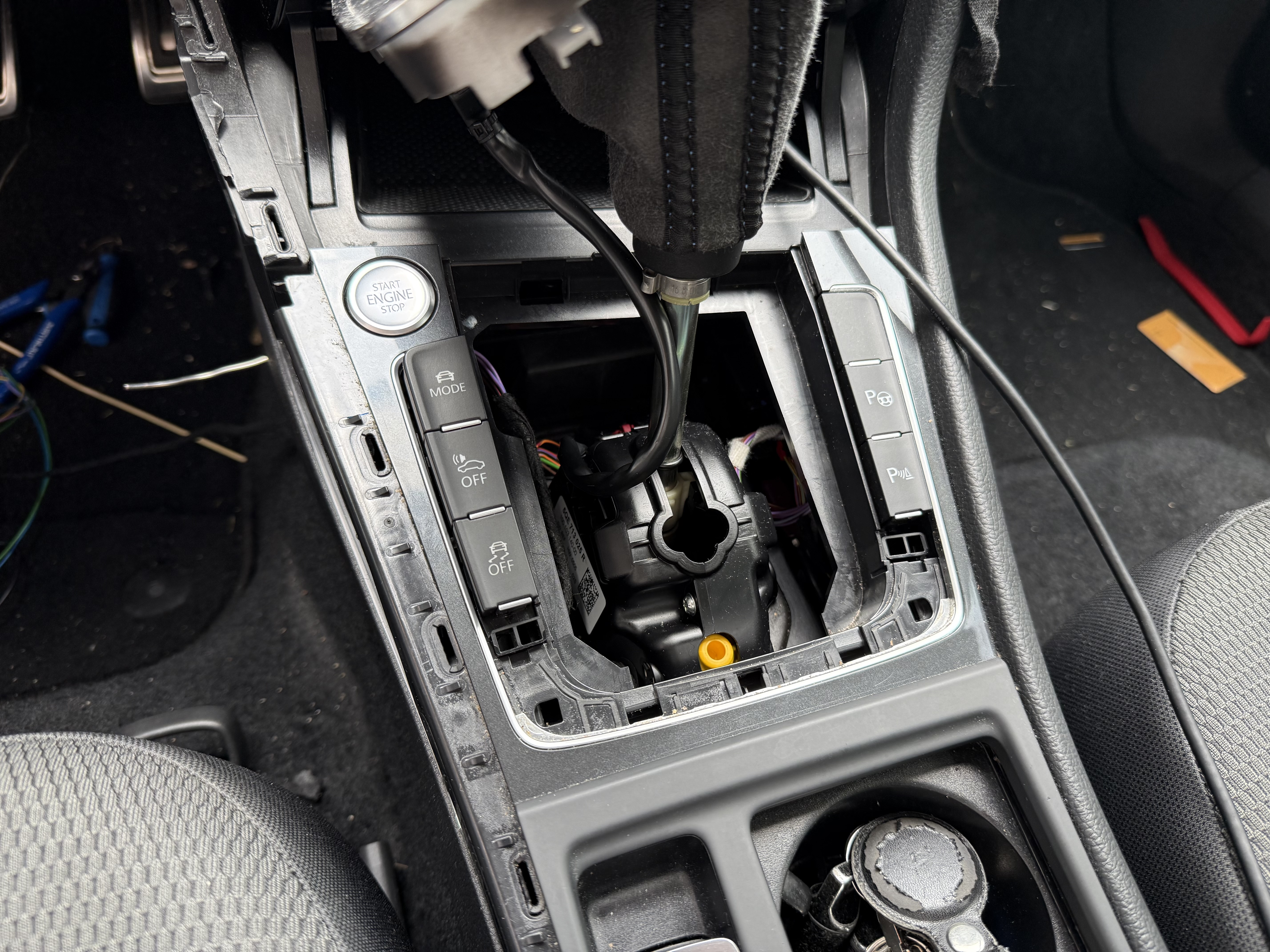
I started with the buttons for the ESC/ASR and e-Sound system. The button module I already prepared before, so I started by removing all the trim pieces around the shifter. This wasn’t so hard, but it took some time to remove all the clips without breaking them. I spent way too much time on trying to remove the old buttons, until I found out that I could simply push them out from below. Duh.
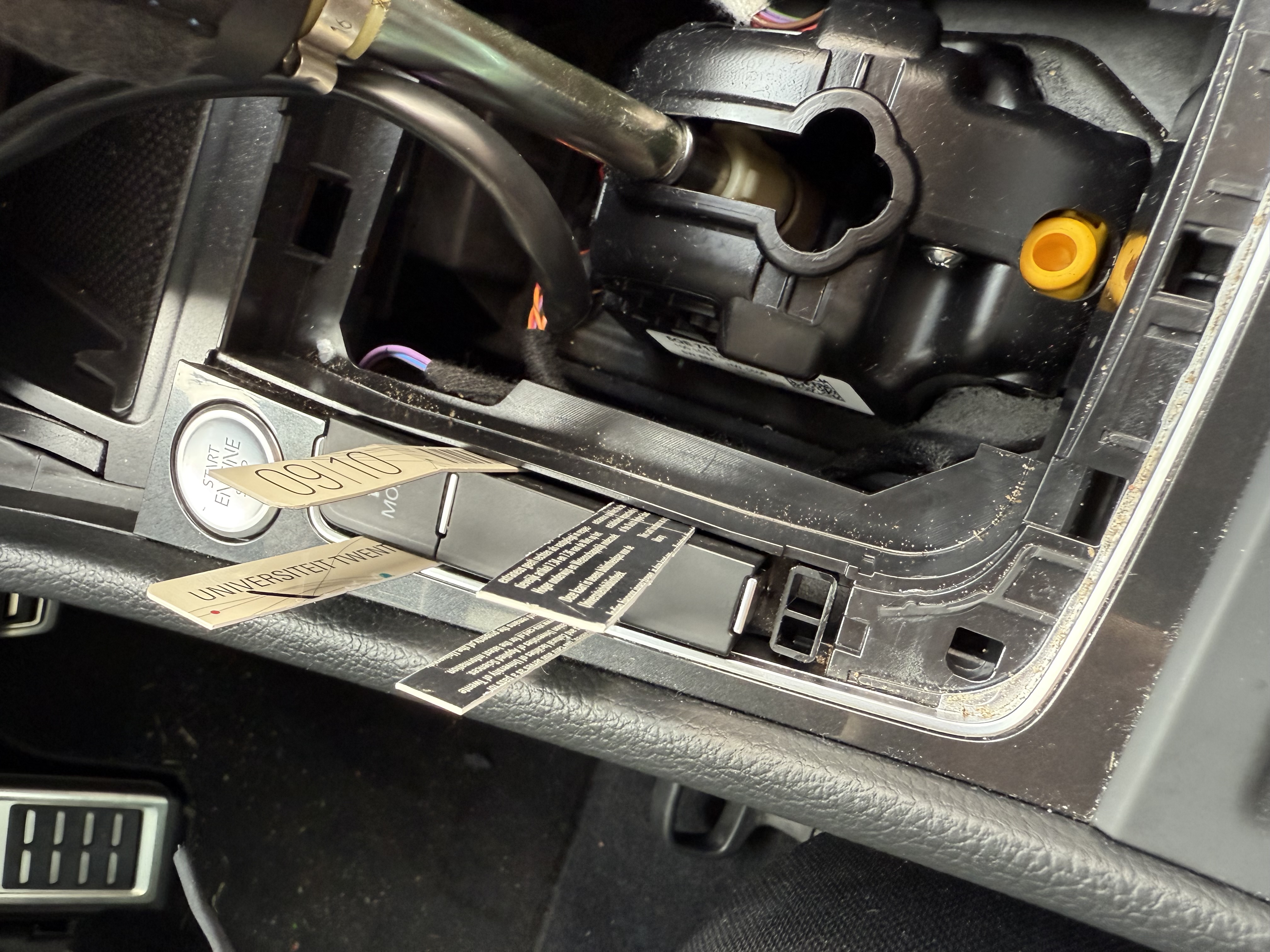
Next step was to connect the buttons to the car. I created a secondary wiring and connected using the following pinout (EX23 is the 10-pin connector on the button module):
- EX23/4 -> T12ab/10 (e-Sound control unit)
- EX23/7 -> T12ab/9 (e-Sound control unit)
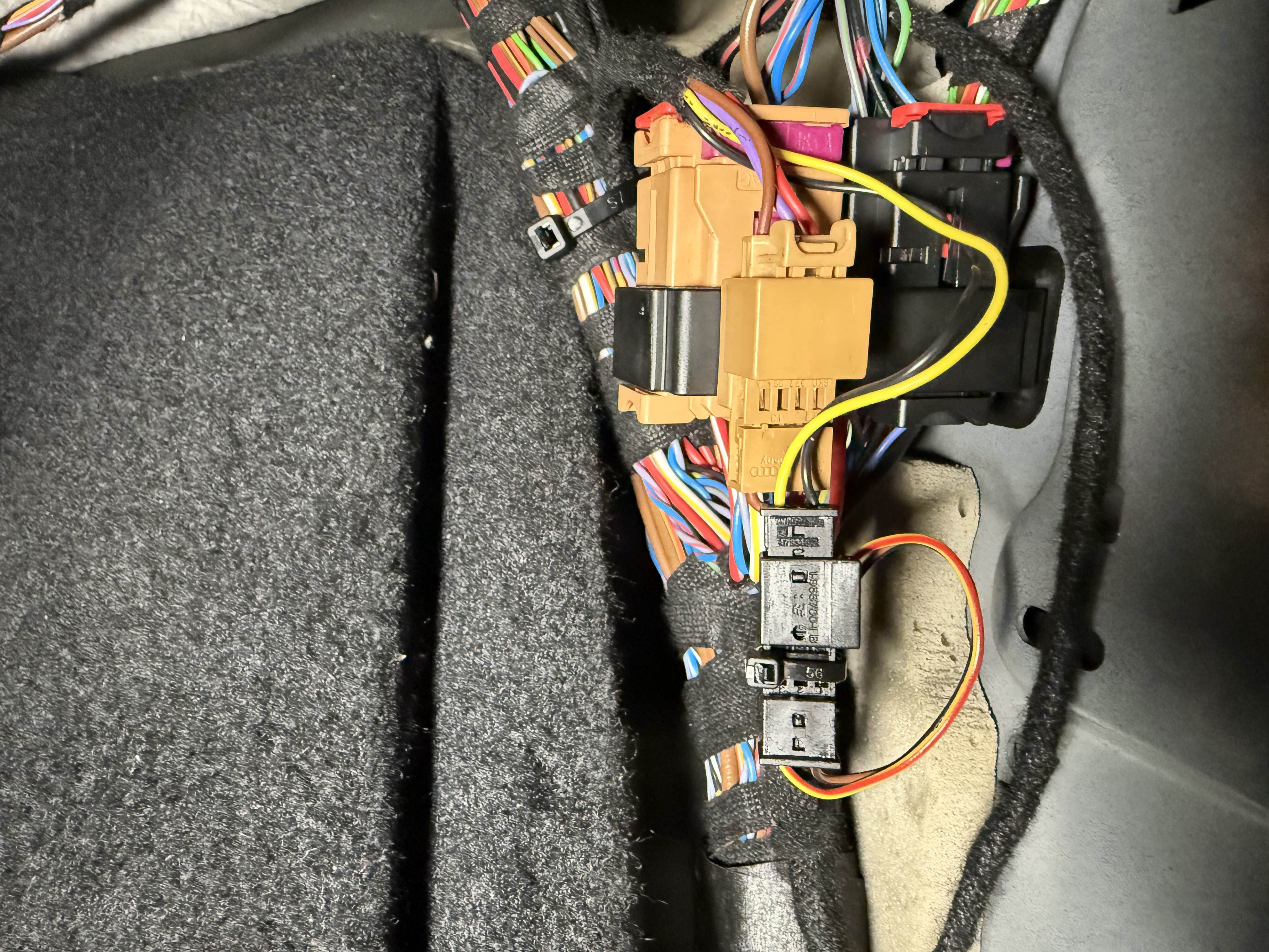
- EX23/9 -> T17d/5 (black connector on the TIUL coupling point)
- EX23/10 -> SC34 (Fuse)
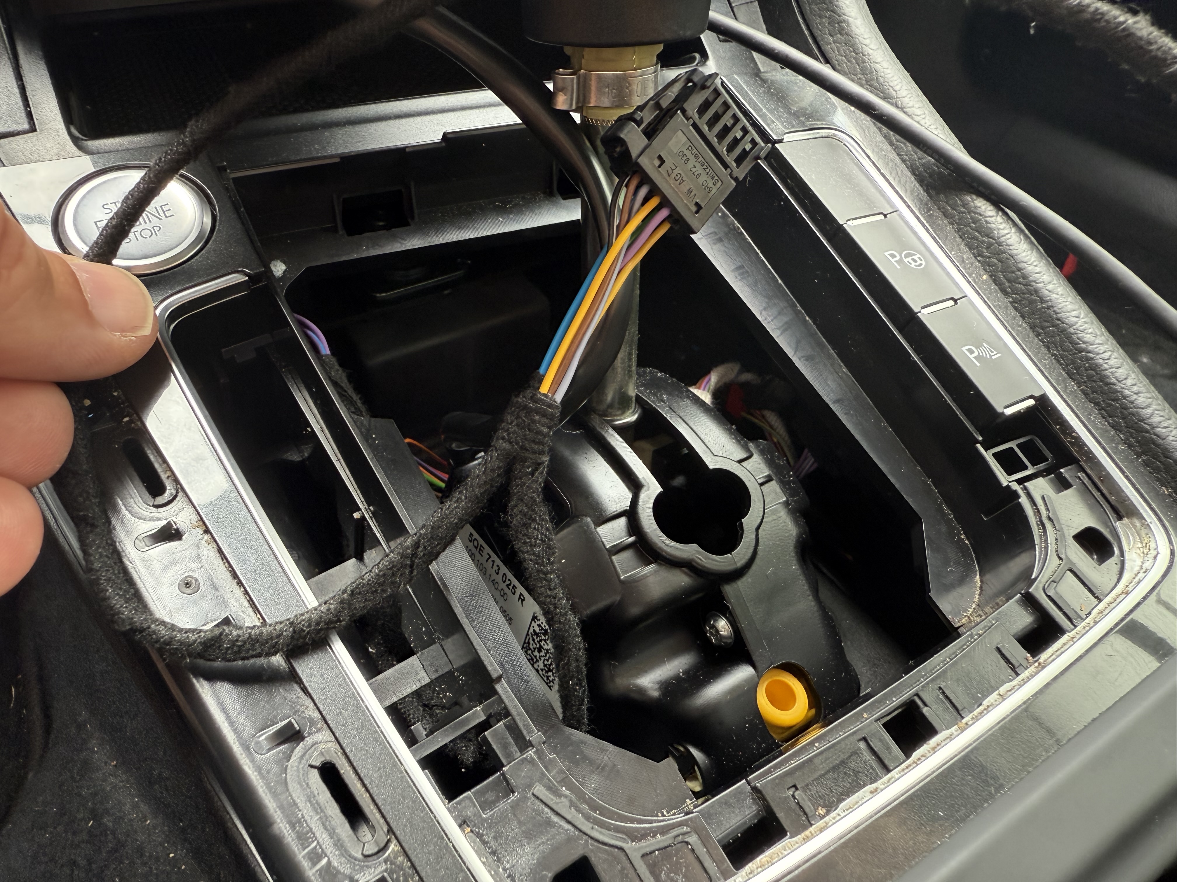
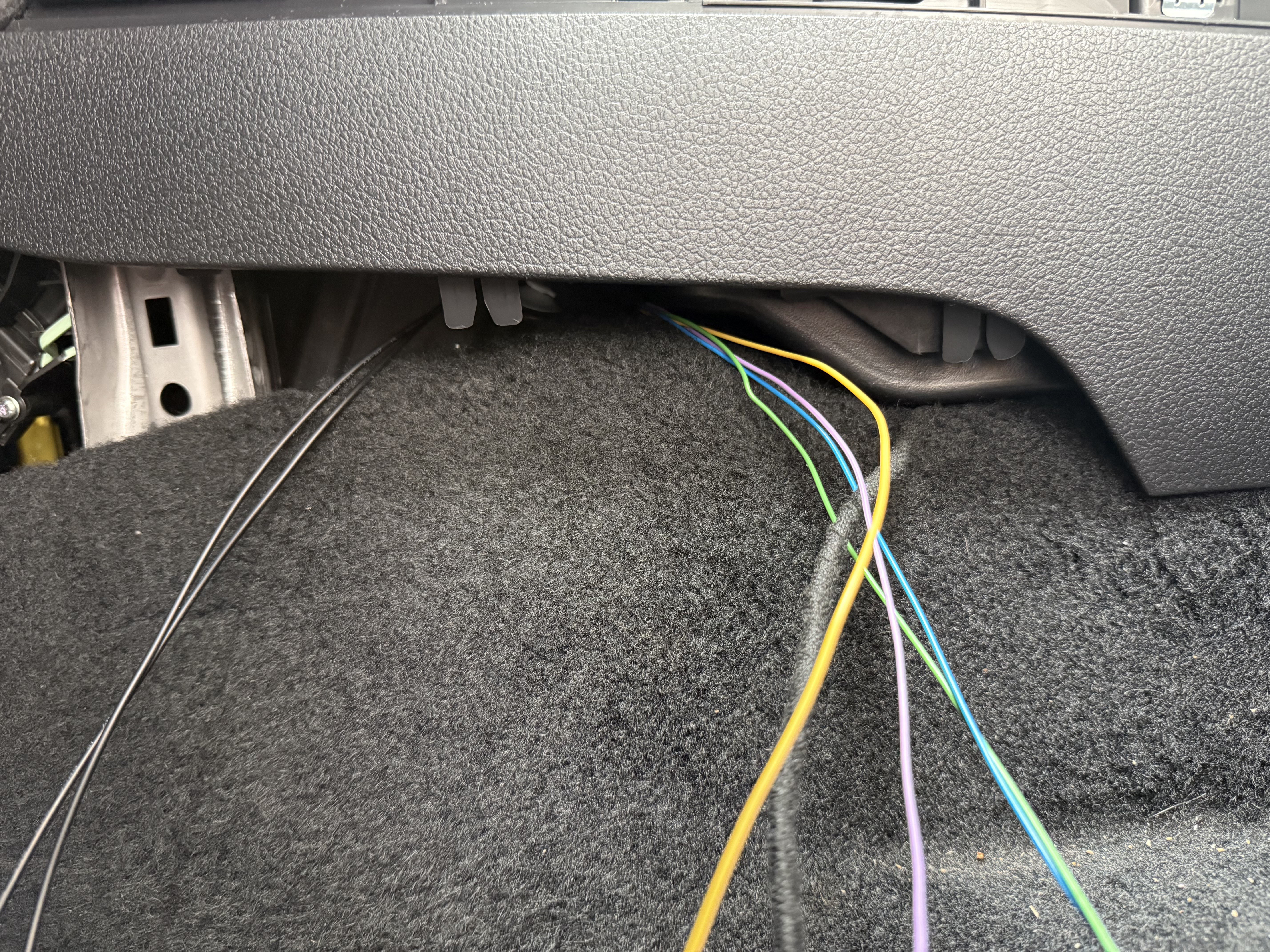
This wiring loom needs to go to the e-Sound control unit. This means it needs to go up to the center console, behind the navigation screen. I spent an aweful lot of time to feed the wires through the narrow space between the carpet and the fresh air ducts, because they have to follow an exact path. Of course, I wrapped the wires in cloth tape.
The e-Sound control module
Next up was the e-Sound control unit. I had already sourced the parts, so I just needed to install it. The control unit is mounted behind the navigation screen in a plastic mounting bracket, so I had to remove the screen and the air outtake ducts first. Addition wires from the speaker (via the TIUL coupling point), the buttons and the fusebox needed to be connected. I have documented the pinout in the first part on this topic.
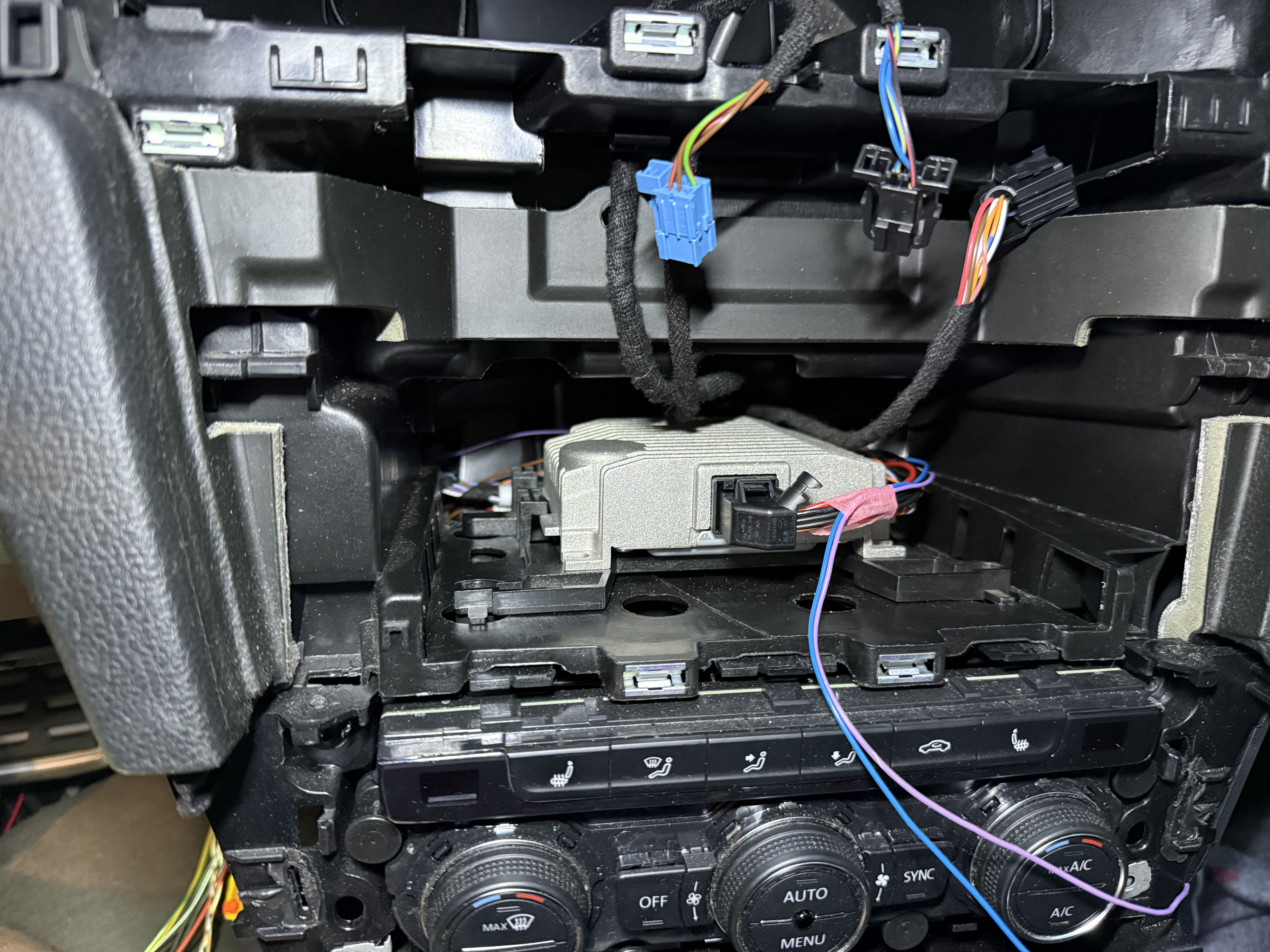
It is not very visible in the photo above, but the wires come in from the left back side, joined together with the wiring loom from the button module. Only EX23/4 and EX23/7 are go to the e-Sound control unit. The other two wires go back with the wires for power and the speaker.
I routed the additional wires as close as possible to the existing main wiring loom under the dashboard, going over the metal support the holds the steering column (not sure). I removed the cluster, which was easy. but installing the wires was a real struggle, for which I removed the front seat so I could lay down and access the area better. But this isn’t made for tall people like me.
In a car with the e-Sound module installed from the factory, it will actually be mounted the other way around. But this way, I have easier access to the connectors. It fits, and does not interfere with the screen. I just need to be careful now, because the navigation screen and the e-Sound control module have the same connector and similar length.
The ambient lighting wiring
Next up was the ambient lighting for the right side of the car. Ambient lighting only uses three wires, a 12V power, LIN-bus and ground. It can be connected in a bus type of network, where you start at one side, and branch off each ‘main’ wire to the next light. For now, I only need to install four lights, but I have plans to extend this to the doors and the dashboard. That means that I will prepare these wires already
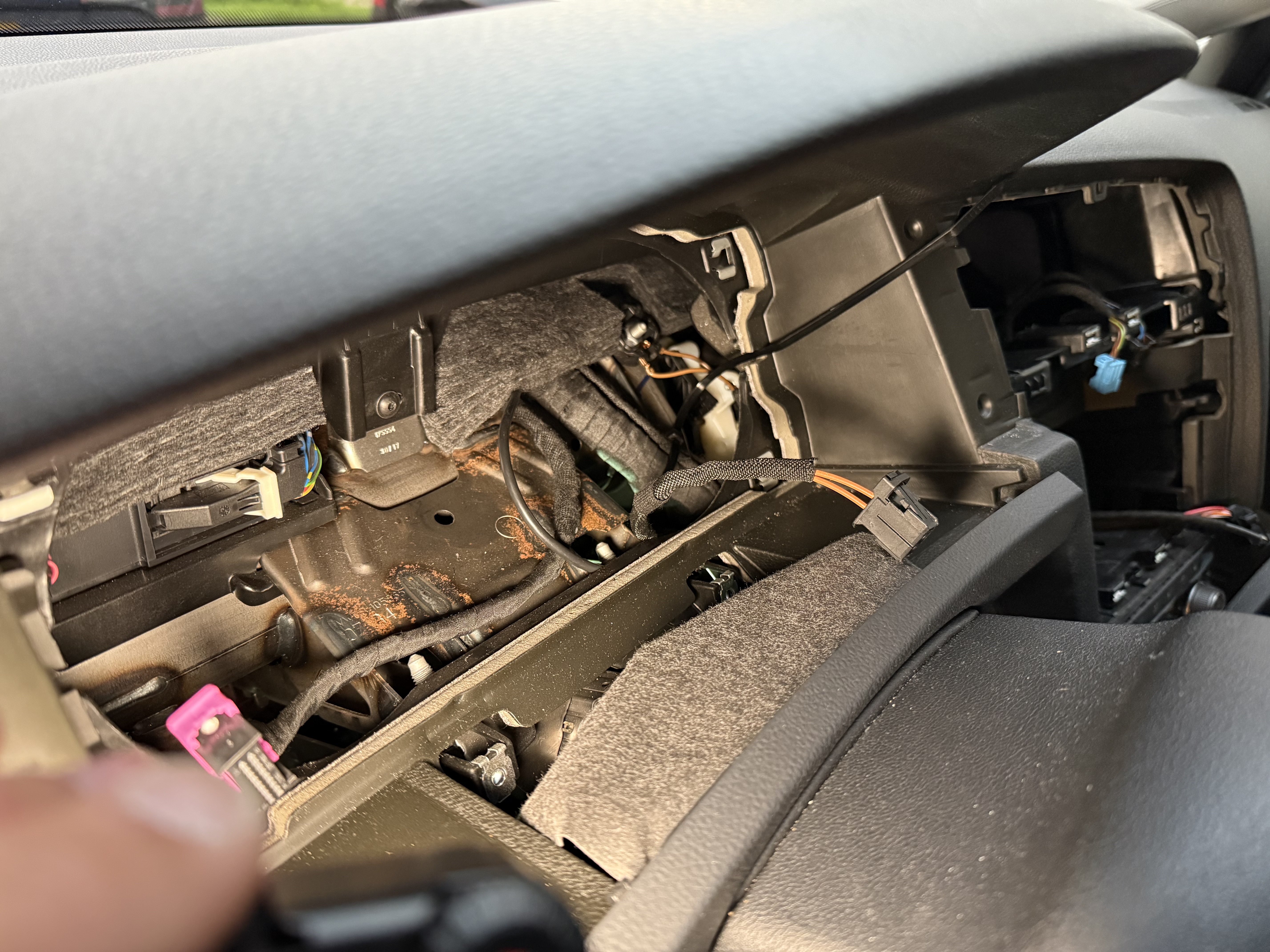
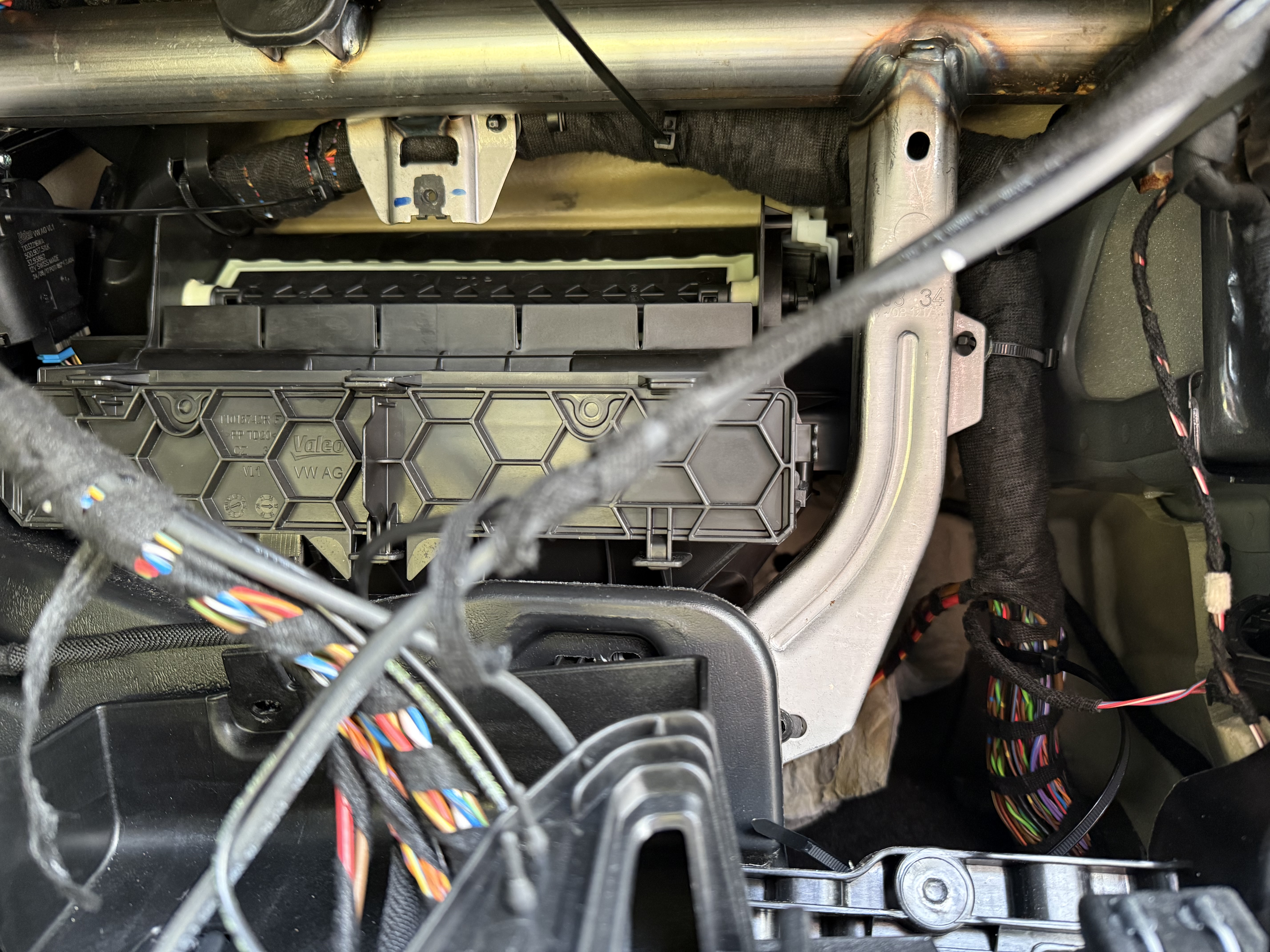
I started at the right side of the car. I could either do it the easy way and tuck the wires just under the glove box, via the center console to the left side. But I could not find a good way to mount them. So I decided to rout them via the main wiring loom, which means I had to remove the glove box. There were many screws, and it took me some time to figure out how to ‘unclip’ it, but I got it out. This beutifully shows the main wiring loom, to which I attached the ambient lighting wires.
On the right side of the car, there is anouther coupling point (TIUR). It had
a free spot for the same connector I used under the seats, the 8K0 972 994.
This made it so much easier, because I could first focus on the wires going
from left to right, then focus on the wires going to the individual lights. I
also used a thicker wire (0.5 mm²) for that wire, and used a thinner wire
(0.35 mm²) for the individual lights. From this connector, I prepared wires
for the dashboard, the footwell, the right front door, the right rear door and
the right passenger seat.
From the photo you can see two additional wires. I want to install puddle lights in the doors, but the rear doors do not have a door module. As an alternative, you can use the door switch and a 12 V power source. For that, I need an additional power wire and ground, so I figured I can better prepare this now, even if I won’t need it.
I don’t have photos of the left side of the car, but there I basically did the same. The only difference is that this part will connect to the fuse box, LIN-bus on the BCM and a grounding point. The wiring loom from the right side eventually joined with the additional wires from the buttons and the e-Sound control unit, but I kept them separate because it is very hard to join the wires mid-way.
The engine bay
The remaining part of work, was to rout the new wires to the proper locations. One wire needed to go to the ABS pump for the ESC/ASR button, two wires needed to go to the speaker in the front bumper for the e-Sound system. This was not hard to do
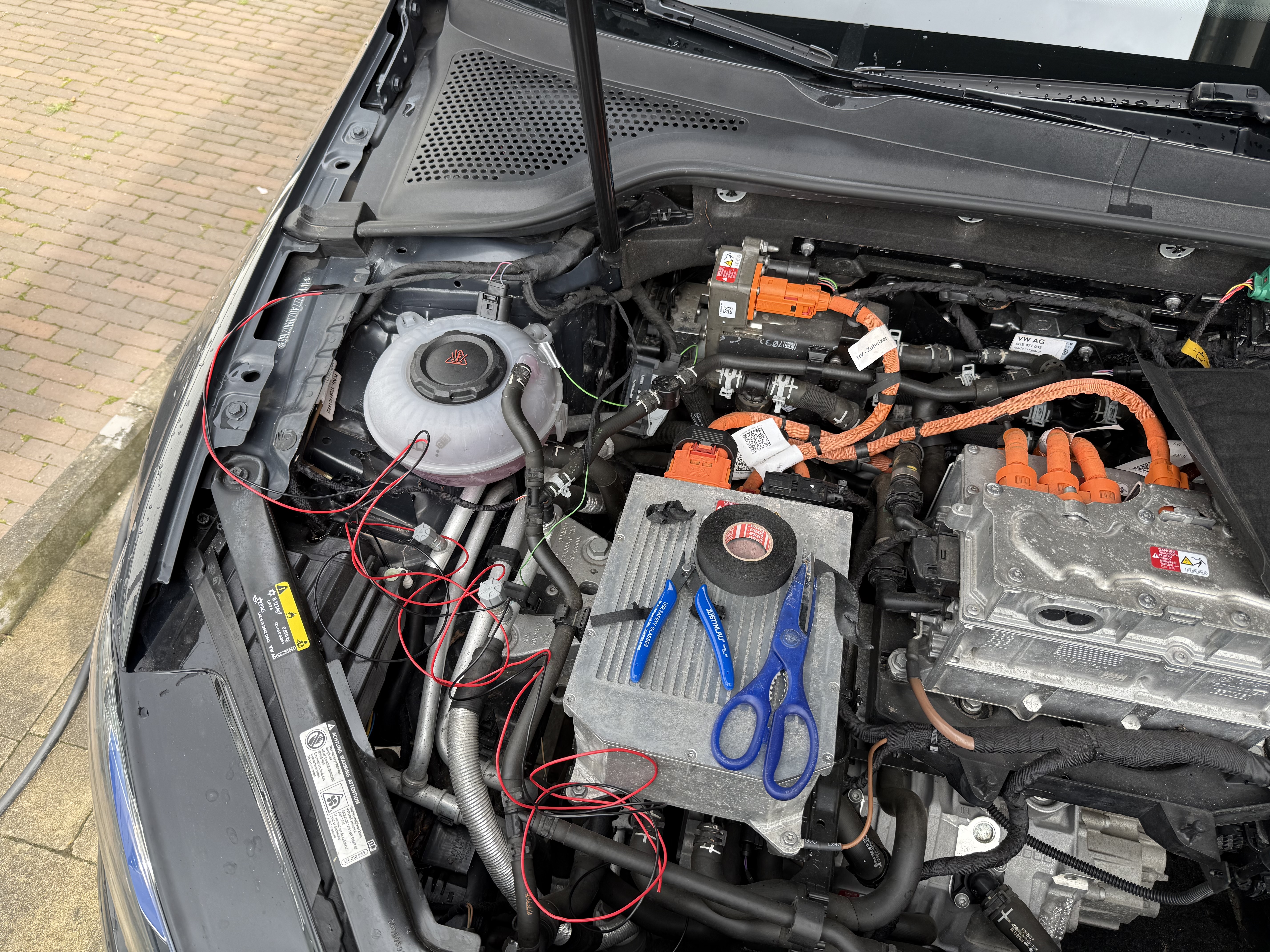
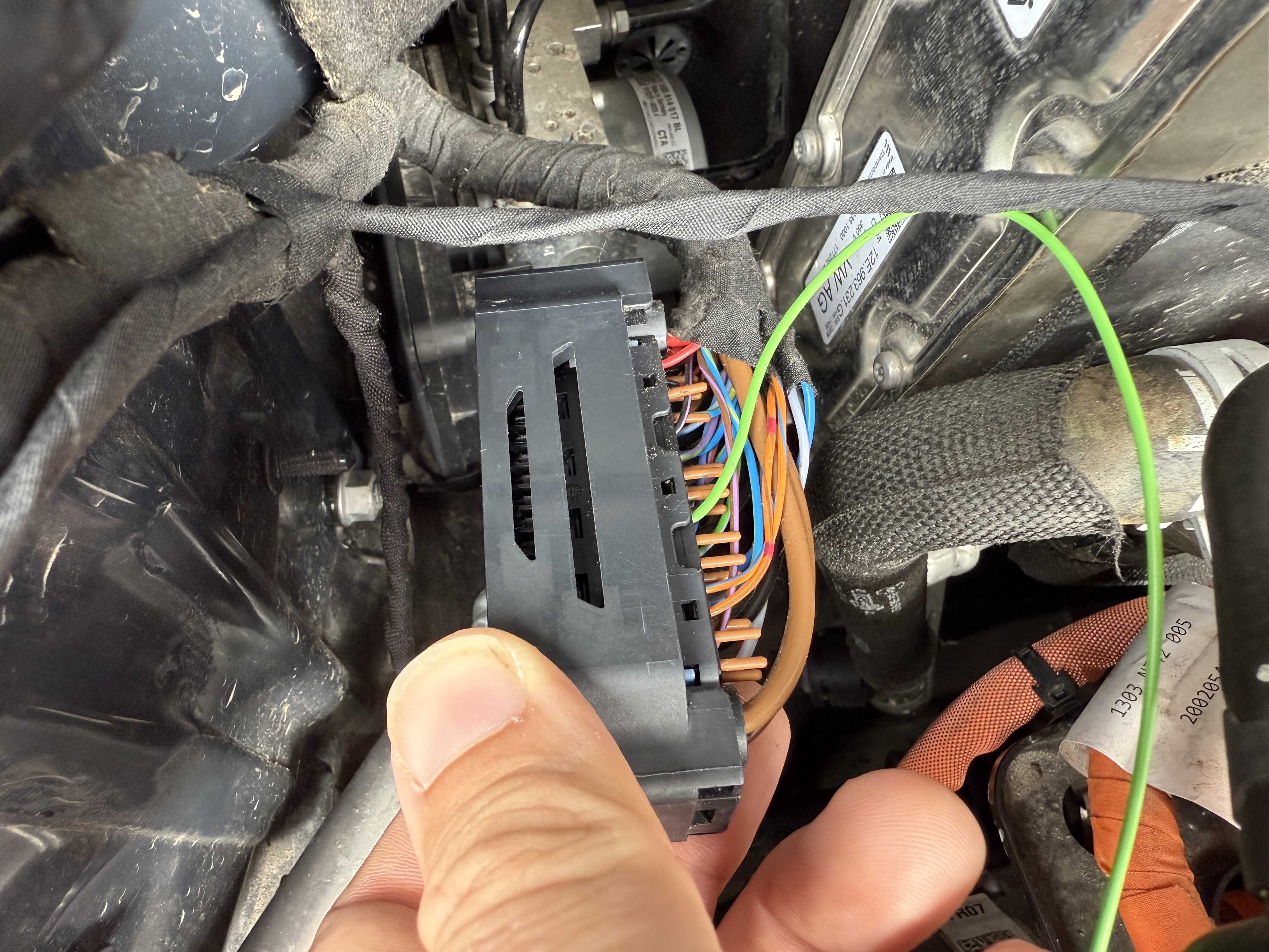
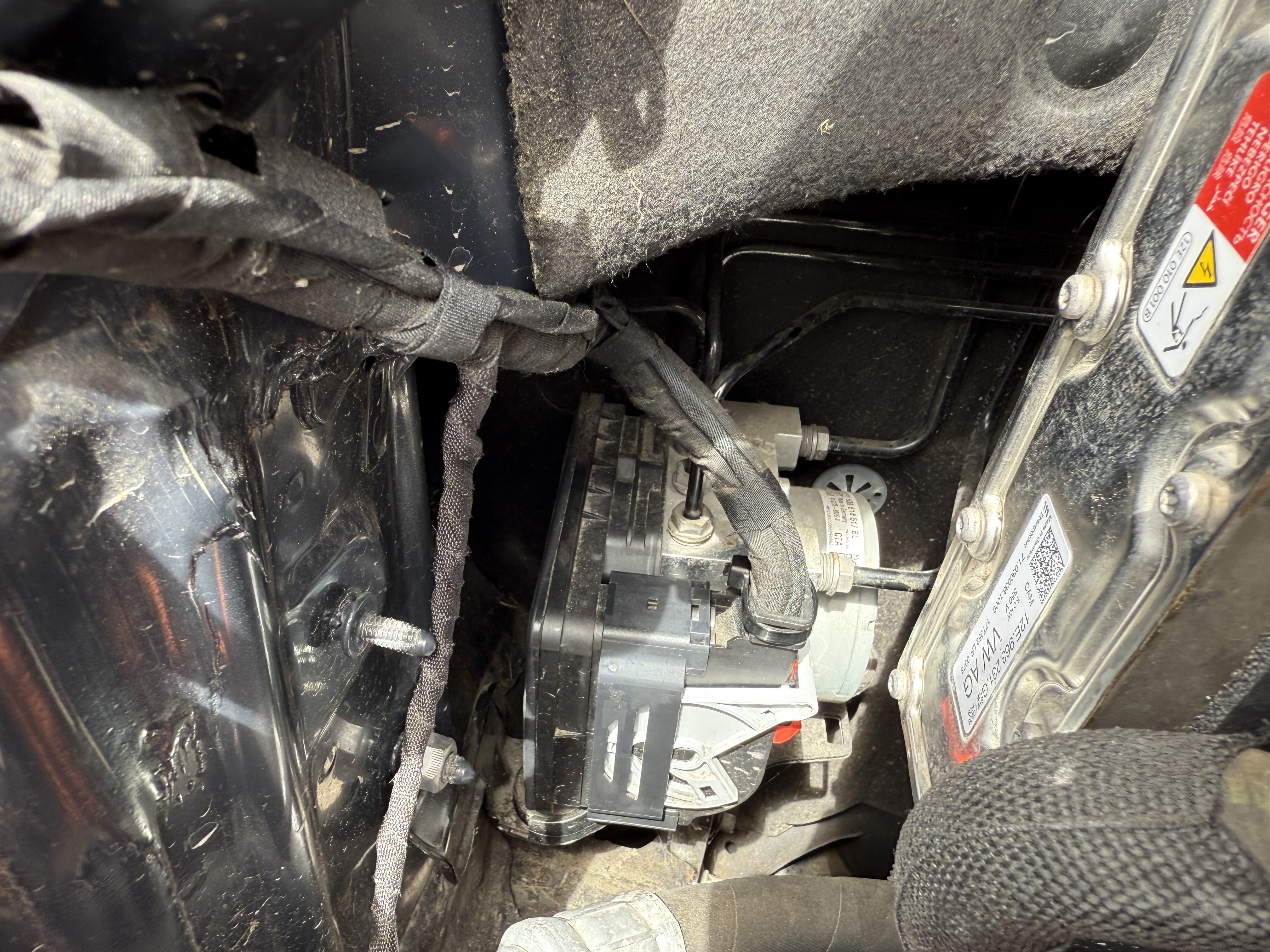
Be sure to handle the ABS pump connector with care when you remove the grey lever. A piece of plastic broke, because I pinched it inward by accident. Luckily, this was not a structural part. I glued it back with superglue, and it seems to hold just fine.
The wires of the speaker followed the same path as the wires for the headlights (I presume). Because I will mount the speaker at a later moment, I simply rolled up the wires and taped them for now.
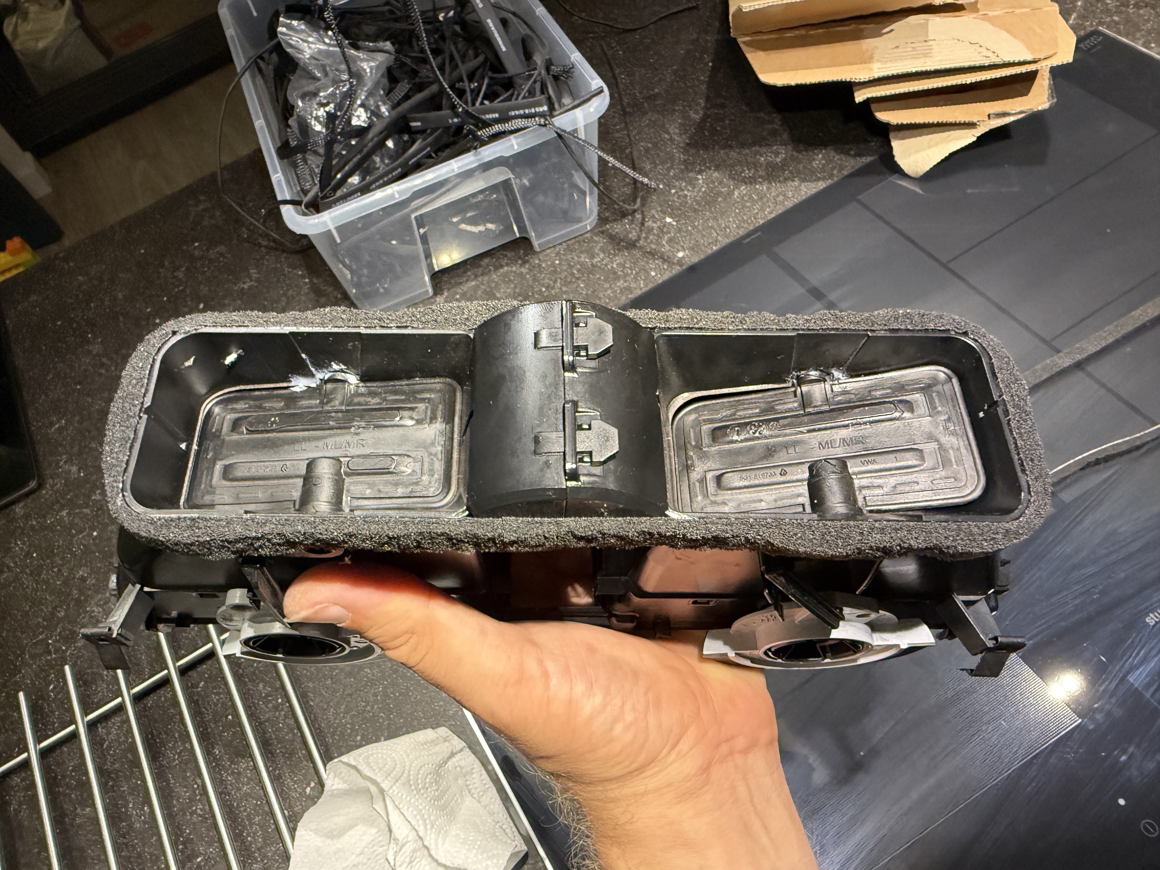
Finishing it up
Once everything was connected, I could give it a quick test and putting trim pieces back. Especially since I knew I had to work around the steering column, I never fully installed the trim pieces back before. I was happy to see that the car became complete again. One thing I had to sort out, was the air outtake ducts. They have been removed before, and the open cell foam that surrounds them was damaged. I could not find the original stuff, but I found something similar, usually used to insulate bridge expansion joints in buildings. The nice thing is that it takes some time to expand to its full width, so I could fit more easily.