e-Sound system (part 3)
Last week I had the time to finish the majority of the wiring that was needed to finish the many ongoing retrofits. After this, I could finally test the e-Sound system and the ESC/ASR button. The ESC/ASR button worked fine, but the e-Sound button did not. I did the obvious checks, such as verifying the wiring, and checking for any fault codes. There was a fault code for the button.
Since I ordered several button modules to combine separate buttons into one, I decided to test the original e-Sound button module (but without the ESC/ASR button). And yes, this one worked. This means that there is some logic inside the button module. The button swap itself was too good to be true.
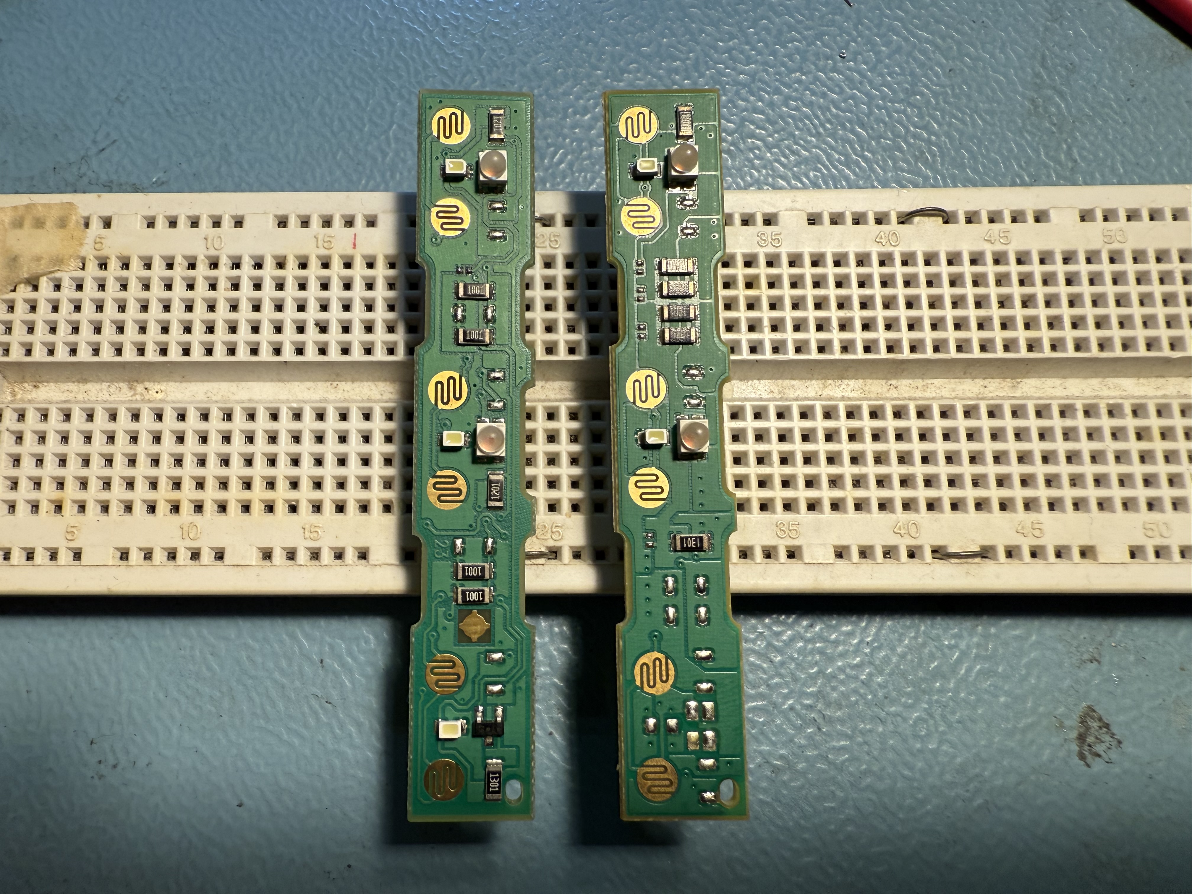
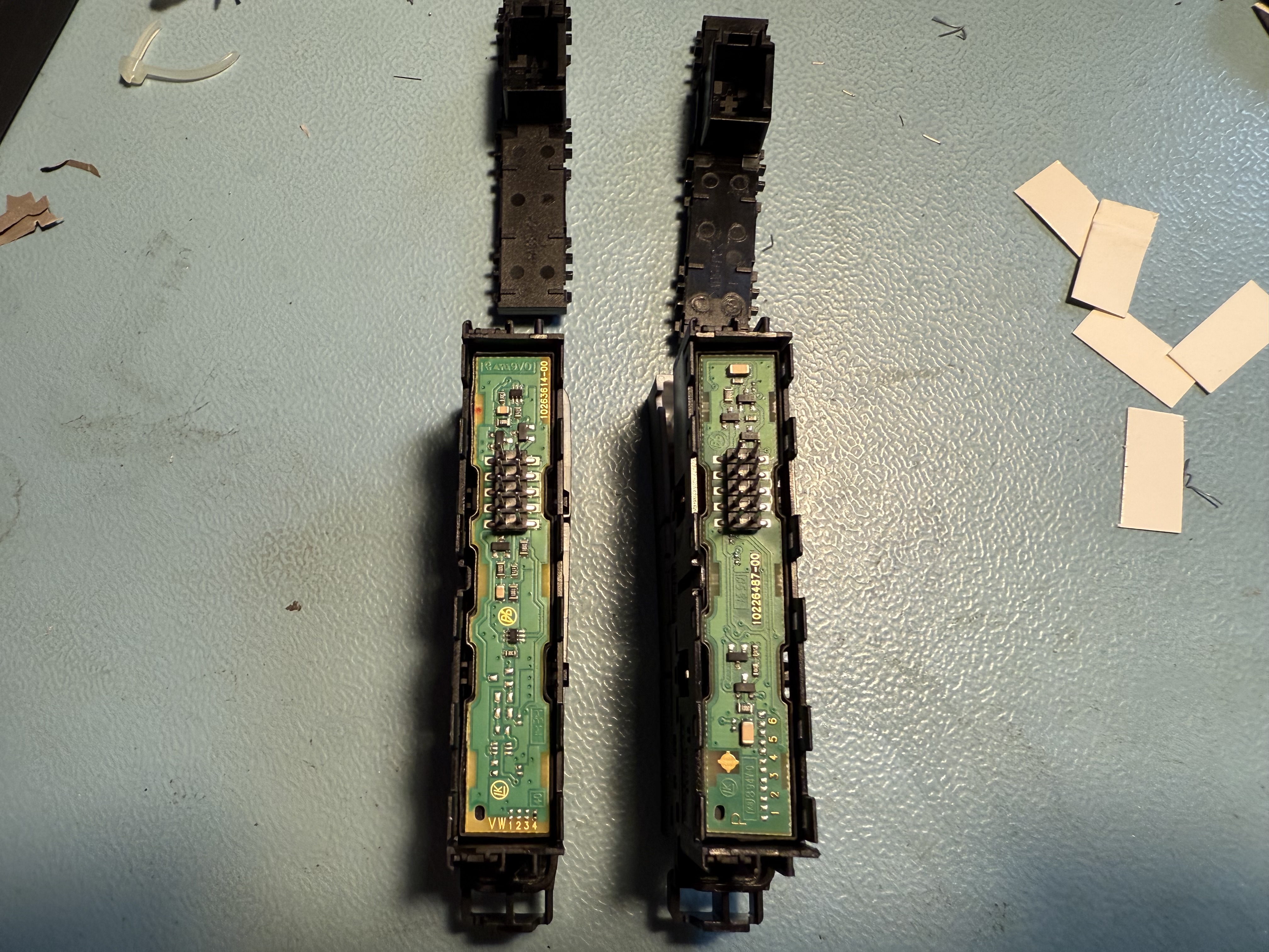
Once I opened up both button modules, I could see some differences on the PCB. There was more parts involved in the e-Sound button module. for that button, parts not needed for the ESC/ASR version.
I knew the wiring was correct. I started to trace the differences, and came up with the following schematic:
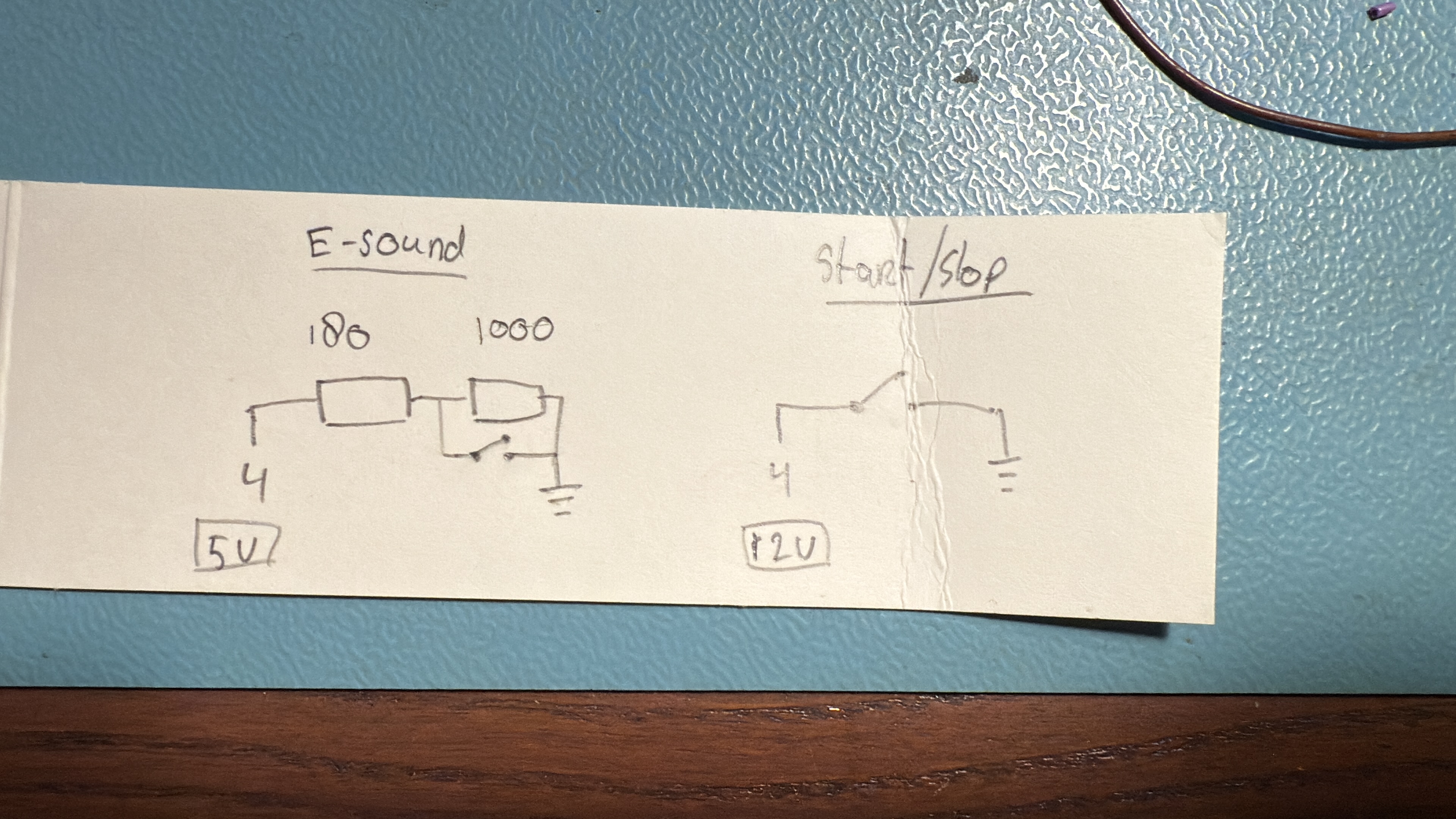
It seems that the e-Sound button module uses a voltage divider to create a voltage level of about 2.5 V when the button is not pressed. Once pressed, this voltage drops to about 0 V. Without these resistors to create the voltage divider, the e-Sound system will measure a voltage of about 5 V, which is higher than the expected 2.5 V. This also explains why it is able to register this as a fault. I find this a clever design, since it is able to detect a wiring fault (open circuit) as well.
I now had to find a way to modify the circuit. Adding the 180 Ω resistor would not be so hard, because I could add this in line with pin 4. But the 1 kΩ resistor has to be connected to pin 4 and ground. I came up with an extension cable that would patch this inside the wiring loom, but it was a bit messy and too long to fit inside the narrow space. I therefore decided to glue two resistors on the board itself.
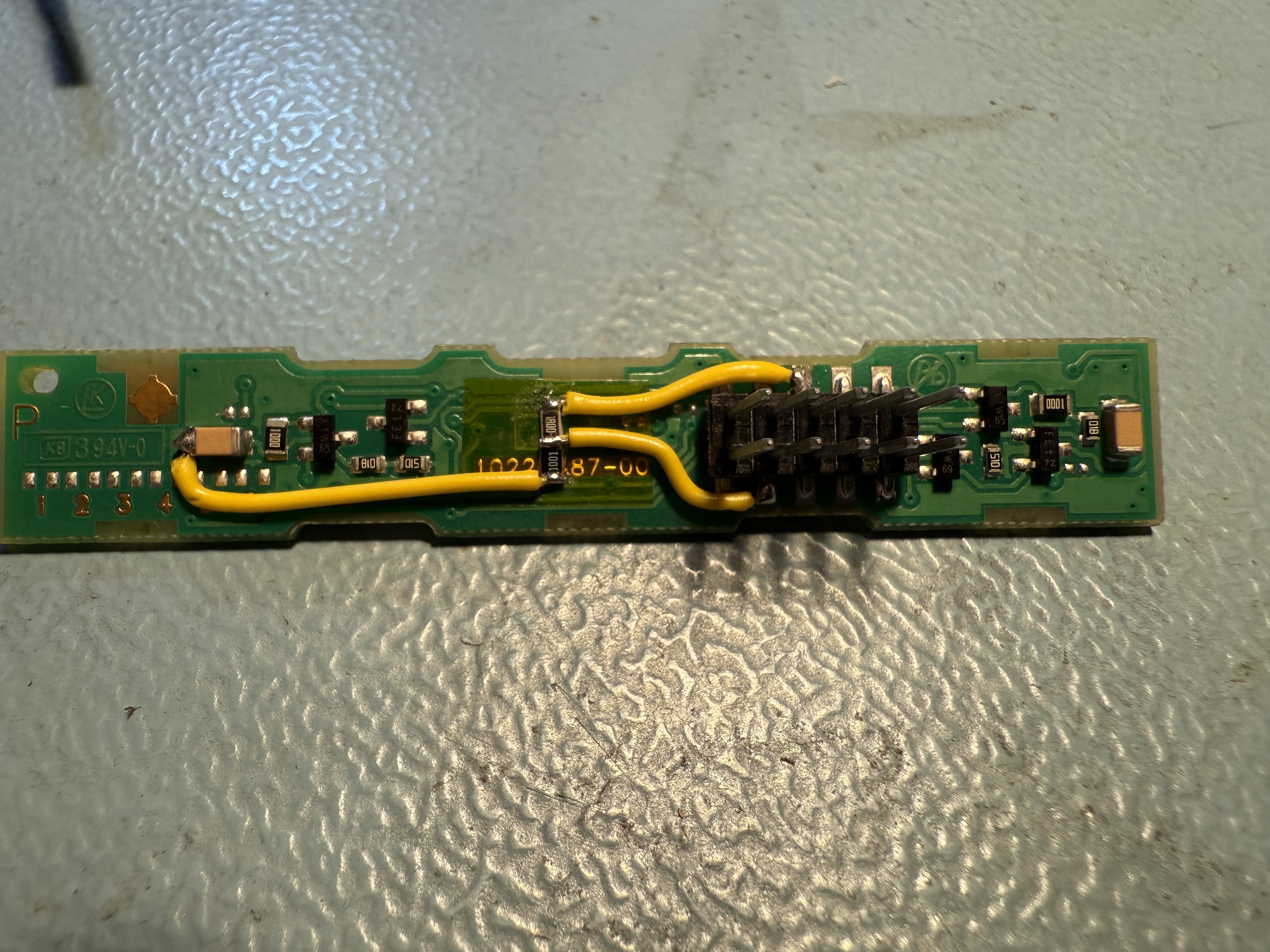
I did make one change to the wiring: I swapped pin 4 and pin 8. I could not add 180 Ω in line with pin 4, because I could not disconnect that pad from the PCB. But pin 8 was unused, so I put 180 Ω in line with pin 8, but still used pin 4 as the ‘center point’ of the voltage divider. This all fits nicely inside the button module. The black part of the 10 pin connector is slightly taller than the wires, so there is enough space.
I tested the button module before putting everything back together, and it worked as expected. The e-Sound system now registers the button presses, and there are no fault codes anymore
One day I could try to design a PCB that fits between the PCB and the 10 pin connector. A flexible PCB is thin enough, so I could ‘intercept’ pin 4 properly and add the resistors there. But for now, this solution works fine.