e-Sound system (part 2)
Now that I verified that the e-Sound system would work yesterday, and that the ESC/ASR button would work as well two weeks ago, I could start with the final wiring loom in the engine bay. I needed to route three wires from the coupling point (TIUL) on the driver side to the right side of the front bumper (two wires for the speaker, 0.75 mm²) and the ABS pump (ESC/ASR button, 0.35 mm²). These three wires need to go through the so-called firewall.
There are two options to route the wires through the firewall. The first one is to use the secondary hole that probably exists for service or repair purposes. The other option is to try to feed the wires throug the existing hole. However, this the cable rubber grommet is taped very well to the wiring loom. The first option would require me to properly seal the hole, so even though option two is the hardest, it was the easiest to seal and the best looking.
I carefully removed the tape around the rubber grommet, and then used a pen tube to push the three new wires through. It definately took some time, and was not easy on the hands, but it worked. Once the wires were through, I determined the final lenght of the wires in the engine bay. I then taped the inside part with cloth tape, and the outside part with heat-resistant cloth tape. I then sealed the rubber grommet with the same tape, such that it looked as original as possible.
The next step was to route the wires behind the cable tray below the windshield. I’m not sure how this tray/area is called, but it is where the wiper motor is installed. Again, this plastic entry point was taped very well, so I removed this too and fed the new wires through. I did not want to remove the left side wiper arm, so it was a bit of fiddling to get it throught.
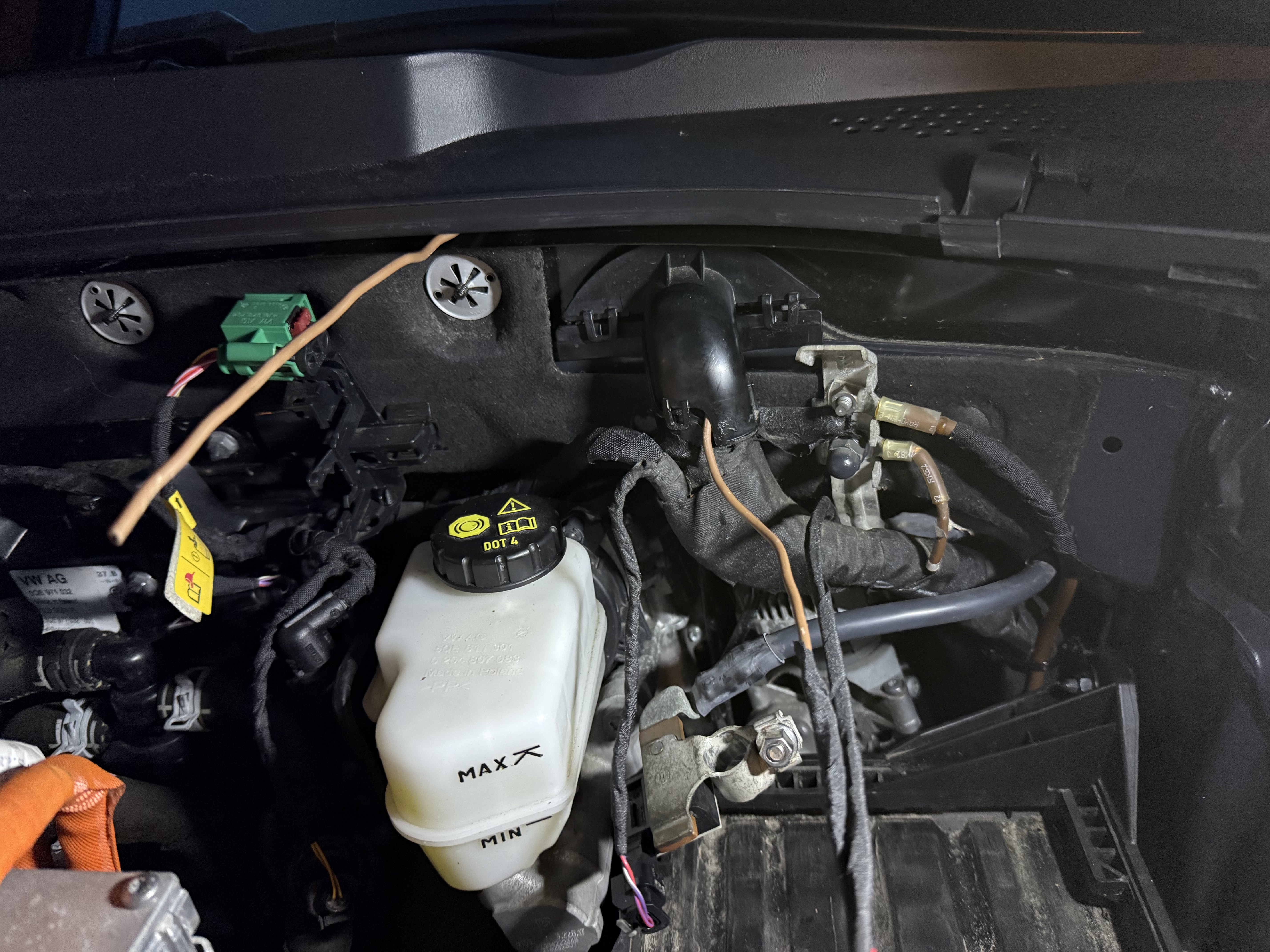
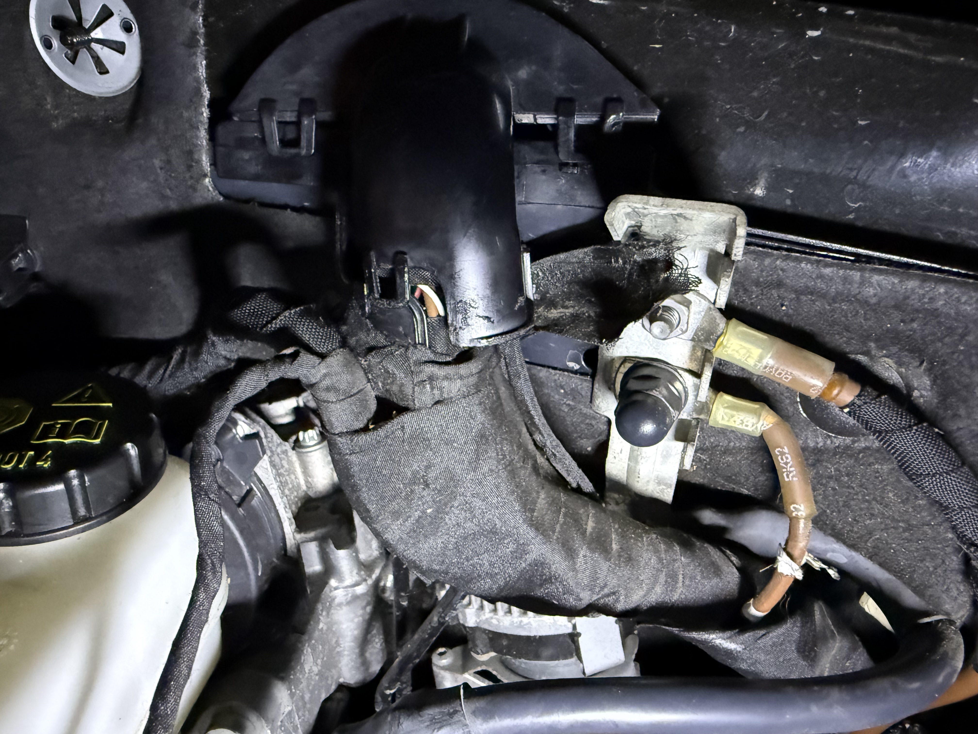
Finally, it had to go through the exit point on the right side of the car. This part was even more taped, so I removed enought to pierce through it. After installing the wires, I sealed it again with the heat-resistant cloth tape.
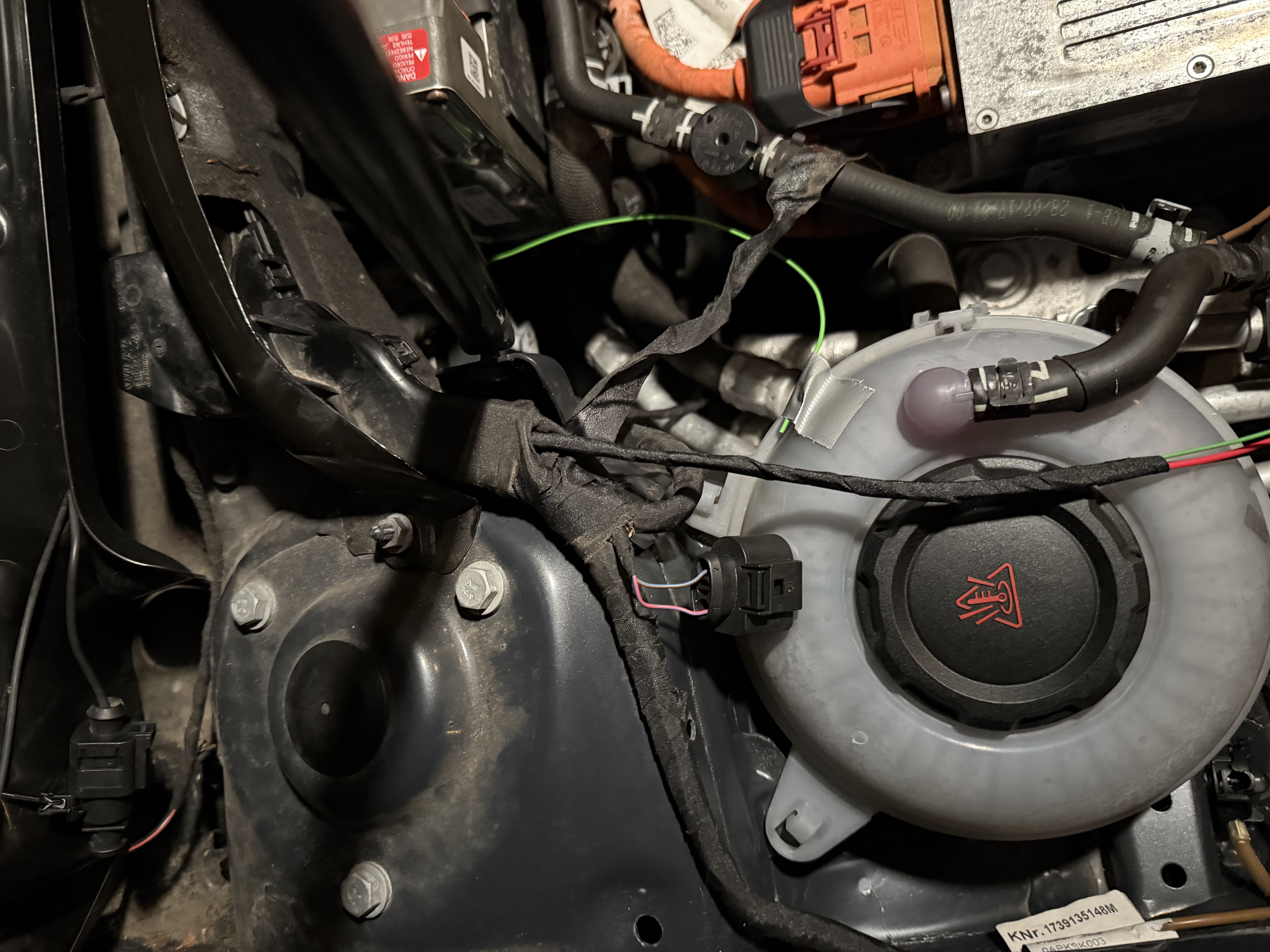
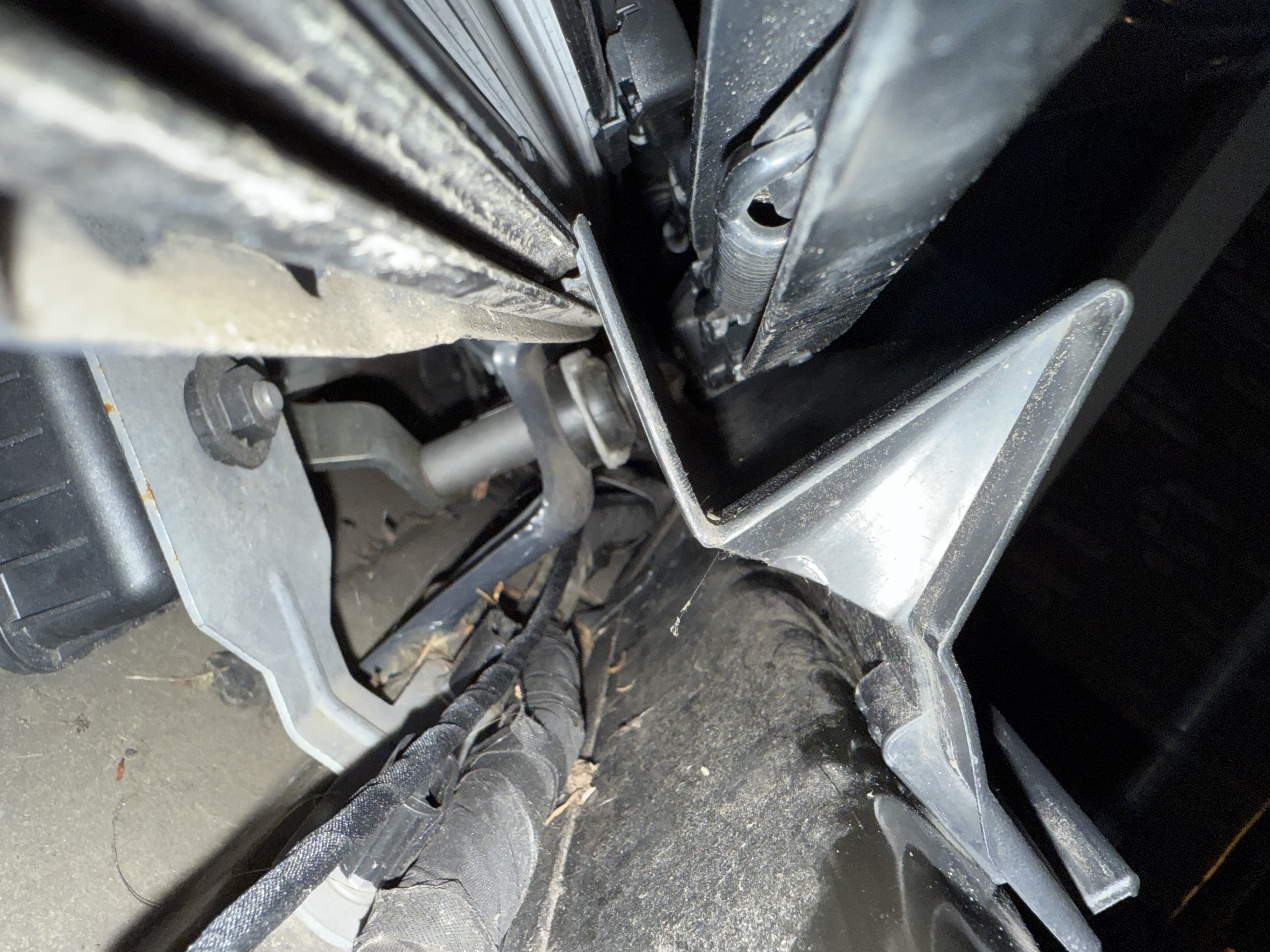
At the exit point, one wire goes to the ABS pump. The other two wires go to the bottom at the right side of the front bumper (left side on the photo). I rolled the wires up, and taped them for now. I will finalize this at a later time.
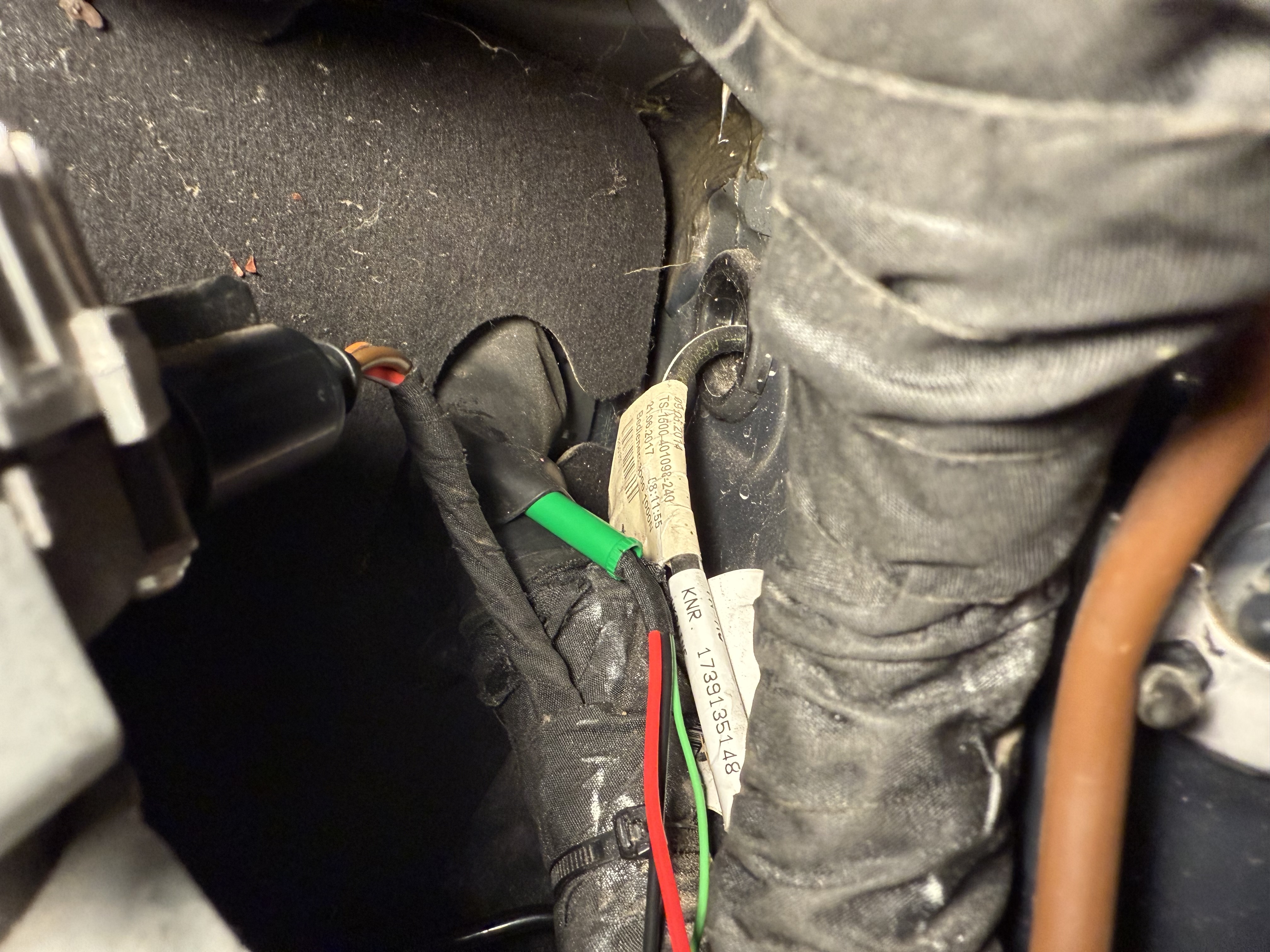
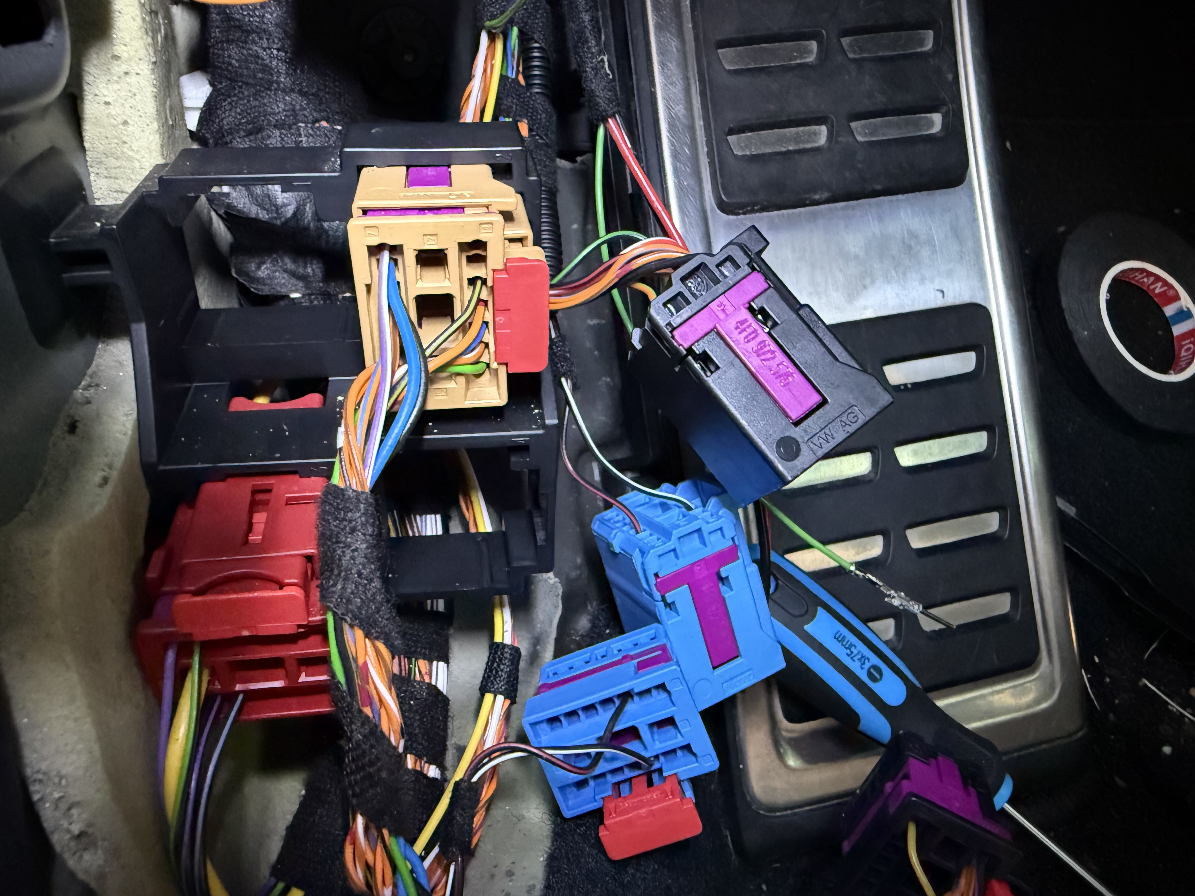
On the inside, I also mounted the wiring loom to the existing wiring loom, and routed them to the coupling point. The ABS wire goes to pin 5 of the black TIUL connector (T17d). The two speaker wires go to pins 1 and 2 of the blue TIUL connector (T17o). Note that the part that is fixed to the mount, is the part of the connector that goes to the main wiring loom and thus to the engine bay.
Crimping the 0.35 mm² pin terminal was not too hard, but for the 0.75 mm² I definitely had a hard time. I don’t own all crimping tools, so I did my best with the ones I have. It took me a few tries to make it work, because initially the crimp was still too thick to fit inside the connector.
For completeness, you will need the following conector pins:
- Female, up to 0.5 mm²:
000 979 034 E - Female, up to 1 mm²:
000 979 159 E - Male, up to 0.5 mm²:
000 979 035 E - Male, up to 1 mm²:
000 979 160 E
Be aware that there are compatible versions of these pins that will fit, but must not be mixed. I’m not sure which ones they are, but I compared them. The proper ones have a copper side/color on the pins.